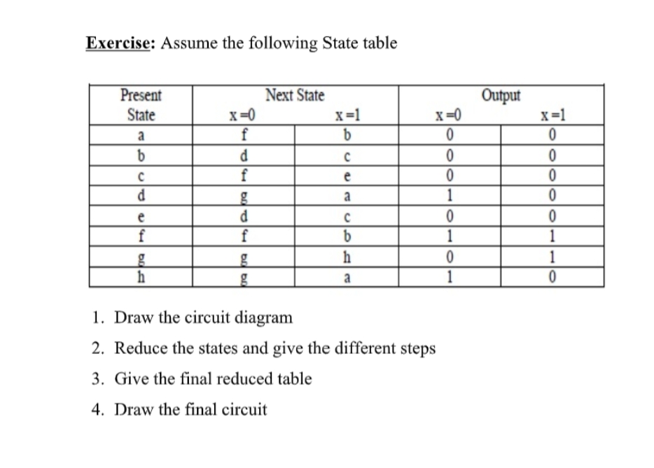
Exercise: Assume the following State table Present Next State Output x=1 State x=0 x=1 x=0 d f e a 1 e f f 1 1 h 1 a 1 1. Draw the circuit diagram 2. Reduce the states and give the different steps 3. Give the final reduced table


Q: 1-(1 2-(1 3-( ar Vrite its equivalent state table. What is the type of this FSM? Write aVHDL code to…
A:
Q: What does a switch statement use to determine the current state of a state machine? O A case…
A: Given What does a switch statement use to determine the current state of the state machine?
Q: Given the expression below, implement the equivalent circuit. X = ABC + ABC + AB Y = ABC + AB + BC…
A: HI THEREI AM ADDING ANSWER BELOWPLEASE GO THROUGH IT THANK YOU
Q: The problem in which output signal is not an exact reproduction of input signal in the power…
A: Given : The problem in which output signal is not an exact reproduction of input signal in the power…
Q: If the state machine given in the figure has present state AB = 11 and input x = 1, then the next…
A: The above circuit is combination of flip-flop(Jk) , 2:1 mux , not gate , clock plus , or gate , and…
Q: A state machine must have at least one input to determine how to transition from state to state. O…
A: Correct answer is True
Q: Refer to the circuit diagram shown below. What is the expression for T2? * A T. B TA 4 T. с T₂ 5 T3…
A: A logical statement which can be true or false, is called Boolean expression. To represent this some…
Q: (b) Describe the state diagram below in detail. Hint: This state machine describes the operation of…
A: State diagram:- A state diagram is applied to show the state of the system. It’s a type of…
Q: What is the output result of the circuit diagram below (O3, O2, O1, Oo)?
A: O3 = S'.I2 O2 = S.I3 + S'.I1 O1 = S.I2 + S'.I0 O0 = S.I1 where S' = Complement of S.
Q: For the following State table: 1. Draw its equivalent state diagram 2. Write a VHDL code that…
A: ANSWER:-
Q: Draw a state diagram and truth table for the following problem: Design a sequential circuit. For…
A: Solution:-
Q: 1-(1 ar 2-( 3-( Vrite its equivalent state table. What is the type of this FSM? Write aVHDL code to…
A: “Since you have asked multiple questions, we will solve the first question for you. If you want…
Q: use matlab program HW 2: Traffic Light System Inputs : C: Color Outputs : Traffic Light Step 1.…
A: As given, we need to write a Matlab program that takes a color as string from user. Then print…
Q: Question1: What is the output of the following circuit: * A > B D- C > A=1 B=0 C=1 A=0 B=0 C=0
A: We are going to find out the output of given logic circuit with given input values of A, B and C.
Q: In figure, A = 1 and B = 1, x= 0 and y = 1. The input B is now replaced by a sequence 101010 the…
A: NAND Latch circuit When A = 1, B = 1 and X = 0 then inputs supplied to second NAND gates are B = 1…
Q: Following state diagram shows a state machine with four different states. Suppose the codes 00, 01,…
A: Answer the above question are as follows
Q: b) Analyze the following circuit as shown in Figure 7. [9] JO QO J PR Q Ck K CL Q % JK-pet J1 Q1 J…
A: Given The answer is given below.
Q: What is the difference between a combinational circuit and sequential circuit? Give example of each.
A: Computer circuits consist of combinational logic circuits and sequential logic circuits.
Q: Draw the diagram of the NFA machine according to the transition table below. I = {a, b}, S= {J, O¡,…
A: NFA : It stands for non-deterministic finite automata and it has a 5-tuple. Given that:…
Q: Given the expression below, build the equivalent digital circuit NOR implementation X = ABC + ABC +…
A: Given logic expressions are, X=A'B'C+AB'C'+A'B' Y=A'BC'+A'B'+B'C' Both contains variables A, B and…
Q: Implement a combinational circuit with three inputs x, y, and z and three outputs A, B, and C. When…
A: Combinational circuit with three inputs x, y, and z and three outputs A, B, and C are as follows:
Q: What does a switch statement use to determine the current state of a state machine? O An input…
A: Given What does a switch statement use to determine the current state of a state machine?
Q: Q.3 For the given state diagram in Figure Q.4, using binary state encoding, derive a state…
A: Given data S0 = Q1' Q0' S1 = Q1, Q0 S2 = Q1 Q0' Given figure
Q: Determine the output sequence and subsequent states that will occur when the 010110111011110 input…
A: The output of current state will be the current state for next symbol
Q: 2. Determine the output C for the system represented by the figure below. R₁ G₁ H₁ R₂ R₂ H₂ G₂
A: ans is given below
Q: 1. Build the circuit shown below and complete the truth table to show correct operation. A B Input A…
A: Here we need to consider output as 3 bit. Let output be Y2Y1Y0 where Y2=A<B Y1=A=B Y0=A>B
Q: Give the state diagram for a sequence detector whose output is 1 only if there is the sequence…
A: whose output is 1 only if there is the sequence 1011(first 1, second 0,third 1, fourth 1) at the…
Q: An asynchronous state machine has two inputs and one output. If the total number of received O's is…
A: an asynchronous state machine has two inputs and one output. if the total number of received o's is…
Q: For the following state diagram fill the table 0/0 0/1 SO S1 00 01 1/0 0/1 1/0 0/1 S3 S4 1/0 11 10…
A: Here in this question we have given a mealy machine.and we have given a incomplete table..so we have…
Q: 1. Determine the Boolean Function of the C, D, E, F, G nodes for the circuit given in Figure 1. D.…
A: Answer is given below .
Q: Given the expression below, implement the equivalent circuit. X = ABC + ABC + AB Y = ABC + AB + BC…
A: For the given two expressions, we will draw their circuit and then we will make circuit table for…
Q: A B C D PO PO POD 1 L D E E F D G b. D PO B F G PO 1. Simulate the circuit and built the truth table…
A: Dear learner, hope you are doing well, I will try my best to answer this question. Thank You!!
Q: An asynchronous state machine has two inputs (X1 and X2) and one output (Z). The output is the same…
A: an asynchronous state machine has 2 inputs (X1 and X2) and one output Z. output is same of previous…
Q: Which of following statement is true about combinational circuits? Question 4 options: A.…
A: Note: we are only allowed to solve one question in one post. I am solving the first on here. To get…
Q: Given the state table below, the output sequence generated by an inpu- sequence X = 1110001 and…
A: Here on each symbol we can transit to one of the 4 states depending on the input. On each transition…
Q: In figure, A = 1 and B = 1, x = 0 and y = 1. The input B is now replaced by a sequence 101010__, the…
A: The diagram NAND latch. And we know that output of latch must be compliment of each other.
Q: Consider the following circuit. a) Label it in such a way that the labels can be used to create a…
A: Question : Label it in such a way that the labels can be used to create a machine. Answer :- No ,…
Q: From the circuit below : A- B- Cin Cout a. From the input signal A,B,Cin draw the output signal S…
A: The given circuit is full adder circuit. The truth table of full adder circuit is as below:…
Q: Draw a state diagram for an FSM with an input a and three outputs, x, y and z. The xyz outputs…
A:
Q: Convert the NFA defined by 8(qo, a) = {qo, q1} 8(q1, b) = {q1, 92} 8(q2, a) = {q2} With initial…
A: In this question, we have the transition function. We need to convert the given NFA to DFA. First,…
Q: Clck state 0 state 1 state 2 state 3 state 4 state 5 state 6 state 7O A BCDEF GH A Draw a state…
A: This is the last in a series of four articles written to introduce you to the most important…
Q: 6. In a(n) circuit, the input values explicitly determine the output. 7. In a(n). existing state of…
A: NOTE: - Hi, since multiple questions are there, so the first three problems are answered below. 6.…
Q: In Figure 1, assume that the outputs not specified in the states B and G are 1 and 0, respectively.…
A: Answer: I have given answer in the handwritten format
Q: Shown in the figure is excitation table of of a counter design. In the FF input table the values of…
A: For the given excitation table of a counter design, find the values of A, B and C in the FF input…
Q: 1. Find and draw the state table E. Find and draw the excitation table . Find and write the FF's…
A: Please give positive ratings for my efforts. Thanks. As per guidelines, we are allowed to answer…
Q: 4. Using MATLAB software, write a program to plot the signal given below. 10 8 4 4 6 8 10 12
A: Code: x=1:11;y=0:10;stem(x,y)
Q: 3) Given the state table, draw the state diagram Present (t) in Next (t+1) out A в у 1 T. 0 0 101 10…
A:
Q: The state diagram given in the figure starts from 00. What state will the system be in when 01011 is…
A: The Answer is in step2

Step by step
Solved in 4 steps with 5 images


- What's the purpose of this circuit diagram? At? Please identify the sandal kind. Why? ndmo ndmo ndmo ndmo ndmo ndmo ndmo is the following state. having a restcreate the state table Reduce the given state diagram and draw the new state diagram draw the circuit diagramStarting from state A in the state diagram given belowDetermine the output sequence and subsequent states that will occur when the 010110111011110 input sequence is applied. Current State A Input Output Next State
- Draw a state diagram for an FSM without inputs. Three outputs include a, b, and c. abc must exhibit the following sequence: 000, 001, 010, 100, repeat. The output only changes on a rising clock edge. The initial state must be 000.choose the correct answer :- 1- Which of the following statements about asynchronous circuits is false? a) Memory elements are easy to design and analyze because they are updated at the same time. b) Updates are fast as they depend on instantaneous and individual propagation delays. c) Power consumption is low. d) Since those Memory elements are updated at different times, their designs and analyzes are difficult. 2- Which of the following is true about Synchronous Circuits? a) Since memory elements are updated at different times, their design and analysis are difficult. b) Updates are common and should take longer than the slowest propagation delay in the circuit. This is why they are slow. c) Power consumption is low. d) Updates are fast as they depend on instantaneous and individual propagation delays. 3- Which option has been given the correct naming of asynchronous memory elements? a) O Holder or latch b) O None c) Memory Element d) Flip Flop 4. Using Set-Reset Latch,…Please explain the main differences between synchronous and asynchronous forms of interaction.
- Draw a state diagram of a High Level State Machine that describes the operation of a pulse generator. The generator should produce a pulse 10 clock cycles long, and pulse when an input goes high. Draw the state diagram of a High Level State Machine that describes the operation of a light sequencer for a traffic light. Green should be on for 100 clock pulses, yellow for 20 clock pulses, and red for 70 clock pulses, for this particular street direction. Assume a slow clock (0.25 seconds to 1 second per pulse). What would the opposing street traffic light requirements need to be? Design a High Level State Machine for a paid parking system, such as the one found at Minneapolis-St. Paul Airport. The system will take your credit card when you drive in, record the number and insure it is valid, and then when you depart it uses the same credit card and time stamp to determine how much to charge you.What is the following situation? In some situations particular input sequences will never occur as inputs to a sequential circuit. In other cases, the output from a sequential circuit is only observed at certain times rather than at every clock time. These situations lead to unspecified next states or outputs in the state table. a. An incompletely specified state table. b. An imperfect state table. c. A partial state table. d. A gapped state table.The fundamental distinctions between synchronous and isochronous connections will be explicated, and an instance of each will be presented.
- PLEASE EXPLAIN ALL STEPSDraw (hand draw or using an online tool) the circuit diagrams that correspond to the following Boolean equations (Do not simplify!): xz + (xy + ~z) ~xyz + yz + x~yThe state diagram given in the figure starts from 00. What state will the system be in when 0 1 0 1 1 is applied to its inputs, respectively, and what does it produce as output.Find the values of the flags(carry, sign, zero, overflow) of the processor status register for the givenexample of two 12 bit no’s in Hex (AB7 + DEF) and draw the circuit diagram also.