Experinent lo. 1 Equipotential and Electrie Fields 3. Uaing the second probe point as a new negative probe point, repeat the procedure to determine another point of maximum meter reading, and record. Continue this procedure until the positive electrode 1s approached. Draw a amooth curve through these pointa on the graph-paper nap. arrangement on the paper, and label the poles N and S. Using a amall compass, trace out (marking on the paper) the magnetic field lines as amooth curves. Draw enough field lines so that the pattern of the magnetic field can be clearly seen. Do not forget to indicate the field direction on the lines. JECTIVES Describe elearly the concept of a force field. Explain lines of force and the associated phyaical interpretationa. Distinguiah betveen lines of force and equipotential, and describe their relationahips to work. HEORY Then, starting again at a new position neaz the negative electrode, repeat these procedures for another field line. Trace out four to Bix field linea in this manner. Do not forget to indicate the tield direction on the linea. 1. Drav dashed-line curves perpendicular to the field lines. QUIPMENT • Field mapping board and probes • Conducting aheets with grids • Conducting paint • Connecting wires DC power supply (10V) • Voltmeter 4. Place the negative probe near the center of the field region, and rotate the positive contact until a position is found that gives a zero-meter reading. Record several of these posnts on the graph paper with a symbol different trom that used for the field lines. Check the zero on the voltmeter frequently, particularly when changing acales. Use the second point as a new pivor point, as before, and determine a series of null (zero) pointa. Draw a dashed-line curve through these equipotential pointa. Determine three to tive equipotential lines in this manner. ROCEDURE lectrie Pield 1. Draw the electrie dipole configuration on a aheet of graph paper to the same acale and coordinates as those of the painted dipole on the imprinted grid on the conducting aheet. Then place the dipole condueting aheet on the board, and set the contact terminala fimly on the painted electrode connectiona. 5. Repeat thia procedure for the parallel linear (plate) electrode configuration. Be aure to investigate the regiona around the enda of the plate electrodea. 2. For the voltmeter, the field probe ahould have tvo contacta mounted about 2 cm apart. Connect the voltage source (10-v de) to the board terminals. Magnetie Field 1. Covering the magneta with sheeta of paper or transparency material, aprinkle iron filanga to obtain an iron filing pattern for each of the arrangementa shovn in Figure my Ponition the negative (-) contact of the tield probe near the negative electrode. Uaing the negative probe point as a pivot, rotate the positive (+) contact around the fixed negative contact until the position with the maximum meter reading ia Tor the bar magnet arrangementa, the magnets should be separated by several centimetera, depending on the pole atrengthe of the magneta. Experiment with this distance so that there is enough apace between the enda of the magneta to get a good pattern. 2. Sketch the observed magnetie field patterns on Figure. After the patterna have been aketched, collect the iron filings on a piece of paper and return them to the filing container. found. Record the positiona of the probe contacta on the graph- paper map. 3. Place the magneta for each arzangement on a piece of graph paper or regular paper. Draw an outline of the magneta for each
Experinent lo. 1 Equipotential and Electrie Fields 3. Uaing the second probe point as a new negative probe point, repeat the procedure to determine another point of maximum meter reading, and record. Continue this procedure until the positive electrode 1s approached. Draw a amooth curve through these pointa on the graph-paper nap. arrangement on the paper, and label the poles N and S. Using a amall compass, trace out (marking on the paper) the magnetic field lines as amooth curves. Draw enough field lines so that the pattern of the magnetic field can be clearly seen. Do not forget to indicate the field direction on the lines. JECTIVES Describe elearly the concept of a force field. Explain lines of force and the associated phyaical interpretationa. Distinguiah betveen lines of force and equipotential, and describe their relationahips to work. HEORY Then, starting again at a new position neaz the negative electrode, repeat these procedures for another field line. Trace out four to Bix field linea in this manner. Do not forget to indicate the tield direction on the linea. 1. Drav dashed-line curves perpendicular to the field lines. QUIPMENT • Field mapping board and probes • Conducting aheets with grids • Conducting paint • Connecting wires DC power supply (10V) • Voltmeter 4. Place the negative probe near the center of the field region, and rotate the positive contact until a position is found that gives a zero-meter reading. Record several of these posnts on the graph paper with a symbol different trom that used for the field lines. Check the zero on the voltmeter frequently, particularly when changing acales. Use the second point as a new pivor point, as before, and determine a series of null (zero) pointa. Draw a dashed-line curve through these equipotential pointa. Determine three to tive equipotential lines in this manner. ROCEDURE lectrie Pield 1. Draw the electrie dipole configuration on a aheet of graph paper to the same acale and coordinates as those of the painted dipole on the imprinted grid on the conducting aheet. Then place the dipole condueting aheet on the board, and set the contact terminala fimly on the painted electrode connectiona. 5. Repeat thia procedure for the parallel linear (plate) electrode configuration. Be aure to investigate the regiona around the enda of the plate electrodea. 2. For the voltmeter, the field probe ahould have tvo contacta mounted about 2 cm apart. Connect the voltage source (10-v de) to the board terminals. Magnetie Field 1. Covering the magneta with sheeta of paper or transparency material, aprinkle iron filanga to obtain an iron filing pattern for each of the arrangementa shovn in Figure my Ponition the negative (-) contact of the tield probe near the negative electrode. Uaing the negative probe point as a pivot, rotate the positive (+) contact around the fixed negative contact until the position with the maximum meter reading ia Tor the bar magnet arrangementa, the magnets should be separated by several centimetera, depending on the pole atrengthe of the magneta. Experiment with this distance so that there is enough apace between the enda of the magneta to get a good pattern. 2. Sketch the observed magnetie field patterns on Figure. After the patterna have been aketched, collect the iron filings on a piece of paper and return them to the filing container. found. Record the positiona of the probe contacta on the graph- paper map. 3. Place the magneta for each arzangement on a piece of graph paper or regular paper. Draw an outline of the magneta for each

Chapter8: Electromagnetism And Em Waves
Section: Chapter Questions
Problem 9Q

Related questions

Question
The topic is about Equipotential and Electric Fields
Minimum of 5 sentences answer
Transcribed Image Text:Experiment No. 1
Equipotential and Electric Fields
3. Using the second probe point as a new negative probe point,
arrangement on the paper, and label the poles N and S. Using a
repeat the procedure to determine another point of maximum meter
small compass, trace out (marking on the paper) the magnetic field
reading, and record. Continue this procedure until the positive
lines as smooth curves. Draw enough field lines so that the pattern
of the magnetic field can be clearly seen. Do not forget to indicate
the field direction on the lines.
I.
OBJECTIVES
electrode is approached. Draw a smooth curve through these
points on the graph-paper map.
Describe clearly the concept of a force field.
Explain lines of force and the associated physical interpretations.
Then, starting again at a new position near the negative
Distinguish between lines of force and equipotential, and describe
electrode, repeat these procedures for another field line. Trace
4. Draw dashed-line curves perpendicular to the field lines.
their relationships to work.
out four to six field lines in this manner. Do not forget to
indicate the field direction on the lines.
II.
THEORY
III.
EQUIPMENT
4. Place the negative probe near the center of the field region,
and rotate the positive contact until a position is found that
Field mapping board and probes
Conducting sheets with grids
Conducting paint
gives a zero-meter reading. Record several of these points on
• Connecting wires
the graph paper with a symbol different from that used for the
DC power supply (10V)
field lines.
Check the
zero
on the voltmeter frequently,
Voltmeter
particularly when changing scales.
Use the second point as a new pivot point, as before, and
determine a series of null (zero) points. Draw a dashed-line
curve through these equipotential points. Determine three
five equipotential lines in this manner.
IV.
PROCEDURE
Electric Field
1. Draw the electric dipole configuration on a sheet of graph paper
to the same scale and coordinates as those of the painted dipole
on the imprinted grid on the conducting sheet. Then place the
5. Repeat this procedure for the parallel linear (plate) electrode
dipole conducting sheet on the board, and
set the contact
configuration. Be sure to investigate the regions around the
terminals firmly on the painted electrode connections.
ends of the plate electrodes.
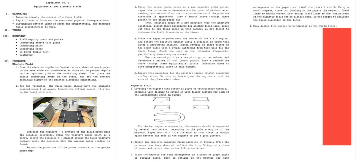
2. For the voltmeter, the field probe should have
Magnetic Field
1. Covering the magnets with sheets of paper or transparency material,
sprinkle iron filings to obtain an iron filing pattern for each of
mounted about 2 cm apart. Connect the voltage source (10-V dc)
to the board terminals.
the arrangements shown in Figure
0000
2832
W699
ic)
For the bar magnet arrangements, the magnets should be separated
by several centimeters, depending on the pole strengths of the
magnets. Experiment with this distance so that there is enough
Position the negative (-) contact of the field probe near
the negative electrode. Using the negative probe point as a
space between the ends of the magnets to get a good pattern.
pivot, rotate the positive (+) contact around the fixed negative
contact until the position with the maximum meter reading is
2. Sketch the observed magnetic field patterns on Figure. After the
found.
patterns have been sketched, collect the iron filings on a piece
Record the positions of the probe contacts on the graph-
of paper and return them to the filing container.
раper map.
3. Place the magnets for each arrangement on a piece of graph paper
or regular paper.
Draw
an
outline
of
the magnets
for
each
2
Transcribed Image Text:VII.
QUESTIONS
1. Why are the measured equipotential lines instead of surfaces for
this laboratory?
Expert Solution
This question has been solved!
Explore an expertly crafted, step-by-step solution for a thorough understanding of key concepts.

Step by step
Solved in 2 steps

Knowledge Booster


Learn more about
Need a deep-dive on the concept behind this application? Look no further. Learn more about this topic, physics and related others by exploring similar questions and additional content below.Recommended textbooks for you
