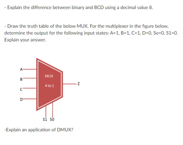
- Explain the difference between binary and BCD using a decimal value 8.


Q: Explain multiplication of binary with block diagram and perform hardware implementation of 12 and 10
A: Binary Multiplication: There are two methods of binary multiplication, (i) paper method and (ii)…
Q: Design a 8 bits DAC and convert the following binary numbers to Analog 1- (10011101)2 = ? 2-…
A: DAC is a circuit which converts the digital input analog output.
Q: What will be the binary representation of 66 DEC in BCD coding system
A: Given: Decimal number 66
Q: Q) Divide a 32-bit number by a 16-bit number and round the reminder for any value. 8086 assembly
A: Function Div32Bit(D1:LongInt;D2:Word):LongInt; Assembler; Asm LEA SI,D1 Mov CX,[SS:SI] Mov…
Q: If you calculate Binary and BCD for a 5 digit number (eg, 33133, 45143, 39175, etc.), they will…
A:
Q: Q12: the length of buss address in 8086: a) 8 bits b) 10 bits c) 16 bits d) 32 bits
A: Address buses is used for carrying memory address from the processor
Q: (i) (ii) Find the binary equivalent of the BCD number (0100 1001 1001.0100 0011 0011)BCD Find the…
A: we need to covert BCD to binary and binary to BCD.
Q: Mention number of FETs for following logic operation: a) 3 input NAND b) 3 input AND c) 2 input OR…
A: A) 3 input NAND- 6 FET
Q: (a) Perform binary addition of the following numbers: 100001101.10111+ 110010100.00010 (b) Represent…
A:
Q: 2- Given a BCD decade counter, show the decoding logic required to decode each of the following…
A: (a) For getting HIGH output when the counter counts 0110, the decoding logic needed for decoding the…
Q: From the following truth table: i) Construct Karnaugh Map (SOP)
A: Note- Since you have posted a question with multiple sub-part. we will solve the first part for you.…
Q: The output of a logic gate is 'HIGH' when all its inputs are at logic 'LOW'. The gate is either O a…
A: a) FALSE, we can design any logic circuit by using only universal logic gate, without using ex-or…
Q: Write the following as eight-bit binary numbers: (a) 97, (b) 101, (c) 197, (d) 222 and (e) 243.
A:
Q: Q7: Find the following for a binary system: capable to represent a decimal number - 589 Number of…
A: The solution can be achieved as follows.
Q: :) A (4-bit) binary counter is connected with DAC to generate a Saw tooth Signal with Frequency of…
A: Given data : Number of bit n=4 Saw tooth signal frequency = 10kHz
Q: Design and draw the logic diagram for a two-input NAND gate using one two-input AND and one NOT…
A:
Q: why 8085 up have 16 bit Address than 80864p Contaim do bit Address
A: 8085 microprocessor: The 8085 is a 8 bit microprocessor which is produced by intel it is…
Q: b) Design and implement a counter with the following irregular binary count sequence 001 010 – 101 –…
A:
Q: THE OUTPUT OF A LOGIC GATE IS 1 WHEN ALL ITS INPUTS ARE AT LOGIC O. THE GATE IS EITHER an AND or an…
A: Given that THE OUTPUT OF A LOGIC GATE IS 1 WHEN ALL ITS INPUTS ARE AT LOGIC 0. THE GATE IS EITHER
Q: Convert the following binary number into BCD. 110010.01
A: The solution can be achieved by first converting binary number to decimal then from decimal to BCD.
Q: The following logic gate represents: a) Exclusive OR logic gate, b) NAND logic gate, c) AND logic…
A: Simple problem on digital electronics. Look below for solution once:-
Q: Q3/ A. Design 4-Bit Asynchronous counter the sequence for the 4-bit binary counter from 0000 through…
A:
Q: ii. Draw logic diagram of half subtractor.
A:
Q: 1- Implement the following function using NAND gates (Use the logic converter in EWB). F=…
A: According to the question, we need to implement the given function using NAND Gate.
Q: Q4: For each of the following set of binary numbers, determine the logic states at each point in the…
A: A 4-bit comparator compare two 4-bit digit. In comparator, the most significant bits are compared…
Q: BE819)16 |binary (1100.101)2 to BCD code conversions: Ren
A:
Q: The IC number of logic gate which is complement of X-NOR gate is a. 7432 O b. 7486 7404 O d. 7400
A: IC 7432 -OR gate
Q: (3) A digital system is required to amplify a binary encoded audio signal. The user should be able…
A: For a digital system we need to calculate the minimum number of bits required to encode in staraight…
Q: Implement a BCD decoder. It should take as input a 4-bit bus representing a BCD digit. It should…
A:
Q: Design the circuit of OR gate with three input using simple logic module ? in digital system
A: OR gate is a logic gate that gives a high value whenever at least one input is high. It is a basic…
Q: A data of 111e is serially transmitted using both binary and BCD? Which encoding technique is faster…
A: Bartleby has policy to solve only 1st question. For solutions of rest questions re-upload them.
Q: i. Write the uses of half adder and full adder. i. What do you understand by carry in addition? iii.…
A: An adder is a digital circuit which performs addition of two numbers.
Q: - Explain the difference between binary and BCD using a decimal value 15.
A: As per our policy, i have attempted 1 question. Difference between binary and BCD using a decimal…
Q: Design and draw out a decoder at the gate level that enables the 4 logic blocks shown below. The…
A: A decoder has few inputs and many outputs. If its inputs are 'n' and its output will be 2n. Only one…
Q: 2. How many X states does a decimal- to-binary encoder have on its Karnaugh's map? (X=don't care) а.…
A: For th equestion the answer is as follows
Q: - Explain the difference between binary and BCD using a decimal value 20.
A: Note :As per our Guidelines we are supposed to answer only 1 question. Kindly repost the other…
Q: Design and draw out a decoder at the gate level that enables the 4 logic blocks shown below. The…
A: A decoder has few inputs and many outputs. If its inputs are 'n' and its output will be 2n. Only one…
Q: Compute the sum of two signed binary numbers below and convert the sum to decimal format. 101010 &…
A: Sum of two binary Number 101010 +100110 01010000 The Sum of two binary Number is 01010000 The…
Q: There is generally some error in the binary representation of decimal numbers. O True O False
A: Decimal numbers can be represented exactly, if we have enough space - just not by floating binary…
Q: (3) A digital system is required to amplify a binary encoded audio signal. The user should be able…
A: Given that, Number of increments = 60. In straight binary, minimum number of bits required to encode…
Q: choose the correct answer The BCD equivalent and binary equivalent of the decimal number 10 are…
A: The BCD equivalent and binary equivalent of decimal number 10 is not same.
Q: Prove the equality of the following boolean expression (AB)'.(CD)'=(AB+CD)'.state this…
A: to prove the Boolean expression (AB)'.(CD)'=(AB+CD)'
Q: Determine the logic required to decode the binary number 1011 by producing a HIGH level on the…
A: The digital circuits are implemented using basic logic gates.The basic logic gates are NOT ,AND and…
Q: Design NOR base SR Flip flop. Take a screenshot of the circuit and also create a table of circuit…
A: S-R Flip-flop- S-K flip flop is known as a universal flip flop that is two inputs S and R. The S-R…
Q: The equivalent value of A in Decimal (Base 10) is 65 and Space is equivalent to 32.
A: Find the equivalent value of 65 in decimal to equals to 32 .
Q: Design a BCD to decimal decoder. NOTE: SUB: DIGITAL LOGIC AND DESIGN(DLD) DEPTT:CS/IT.
A: BCD to decimal decoder: Let ABCD be the BCD number and D0,D1,.....D9 be the output decimal number.
Q: The octal equivalent of the answer in the addition of two binary numbers (1010) and (0101) is
A: We need the octal representation of the given addition.
Q: (b) Draw a block diagram of 3 bit synchronous binary counter.
A: 3-bit binary synchronous counter design :
As per the Bartleby policy, you can ask one question at a time so please ask the second and third questions separately.
Binary number contains only two number 0 and 1
BCD (binary coded decimal) is special form of the binary number in which each deciman digiti can be represented by the four bits.

Step by step
Solved in 2 steps with 1 images


- Design a circuit with a truth table that converts a number between 0 to 7 in decimal to binary then passes it to another component that outputs the number in the output line of the decimal number. Demonstrate the value of input and output using '7'. Discuss the process in your own words. [Hint: The number passes from encoder to decoder. Consider there is no enable pin in the decoder.]When the value of the four-bit N number consisting of W, X, Y, Z variables is N <3 or N> 6, the circuit with a logic 1 output is designed with 8x1 MUX. When the W, X, Y variables are mutually connected to the S2, S1, S0 selection terminals of the multiplexer, in which case are the signals to be connected to the input terminals of the multiplexer correctly? (The variables will be used in the given order and W is MSB. The signals to be applied to the input terminals are written from I0 to I7.)i) Construct a 4-to-1 Multiplexer and provide a picture or snapshot of the circuit here. ii) Use the multiplexer you have constructed in part i)to implement this circuit: F(A,B,C) = ∑m(0,3,4,7) Provide a truth table and a picture or snapshot of the circuit here.
- choice correct answers analogReadResolution() instruction accept bit resolution up to 16 12 32 the maximum of the programmed board - For Arduino ZERO, using 2.23 V built in reference, what is the input code if the default bit resolution was used for Vin = 1 V? 458 1836 459 1837 - For memory address (133F7) h with offset of (2031) h, what is the segment address? 15442 113C 33701 135F41 - What is the input for Arduino UNO if the input voltage is 3.25 V? Assume defaults 1008 644 645 1007Please answer this question in 10 mins i will surely rate your answer. 1. A combinational circuit adds either a 1 or 2 to a 4-bit binary number A. Assume that the inputs bb A3, A2, A1, A0 represent the 4-bit binary number. Another input is a control signal C. The circuit has outputs assumed to be X3, X2, X1 and Xo, which represent the 4-bit number X. When C=0, X=A+1 and when C=1, X=A+2. Assume that the inputs for which X > (1111)2 will never occur. Show the design steps in detail including truth tables, K-Maps, logic equation minimisation. Finally, design this circuit using only NAND gates and inverters .A digitized voice channel is made by digitizing a 4-kHz bandwidth analog voice signal. We need to sample the signal at twice the highest frequency (two samples per hertz). We assume that each sample requires 8 bits. What is the required bit rate? a. 64 kbps b. 32 kbps c. 128 kbps d. 16 kbps
- In cases where the value of the four-bit N number consisting of W, X, Y, Z variables is N <6 or N> 10, the circuit with a logic 1 output is designed with 8x1 MUX. When the W, X, Y variables are mutually connected to the S2, S1, S0 selection terminals of the multiplexer, in which case are the signals to be connected to the input terminals of the multiplexer correctly? (The variables will be used in the given order and W is MSB. The signals to be applied to the input terminals are written from I0 to I7.) A 1,1, Z',0,0,Z,1,1 B 1,Z',0,Z,1,1,1,1 C 1,0,0,0,Z,1,1,1 D 1,1,Z',0,Z,0,0,0 E 1,1,1,0,0,Z,1,1Given: The 16-to-1 Multiplexer's inputs are w0, w1, w2, w3, w4, w5, w6, w7, w8, w9, w10, and w11. The last four inputs aren't connected to an input signal. Task: How many select bits are needed in the 16-to-1 Multiplexer? Draw the schematic of the 16-to-1 Multiplexer, showing inputs and outputs.3) Design a 4-to-16 line decoder using only 2-to-4 decoders. (Hint: Using a truth table of the 2-to-4 decoder might be useful.) 4) What is the problem in an encoder if more than one input is 1 at the same time? Design a 4-to-2 priority encoder (Truth Tables, K-maps, and logic expressions) to ensure that only one input will be encoded at the outputs
- From the function below; try solve this by karnaugh map. 1. how many output variables there are?2. what is the value of entry #3 if A is the most significant bit and C is the least significant bit?3. find the minimum function in the sum of products using karnaugh mapQ = ∏ (0,2,4,6,7) expression is desired to be designed with 3 to 8 decoder. To which outputs of the decoder should the inputs of the or gate be connected to make this design? (Z and A are LSB. Is the product symbol.) A Q2,Q4,Q6 B Q0,Q4,Q7 C Q0,Q2,Q4 D Q3,Q5,Q7 E Q1,Q3,Q5Hello can you make a truth table from this decoder Assignment: 1.png Sample picture on how to make the truth table from that decoder: samplee.png