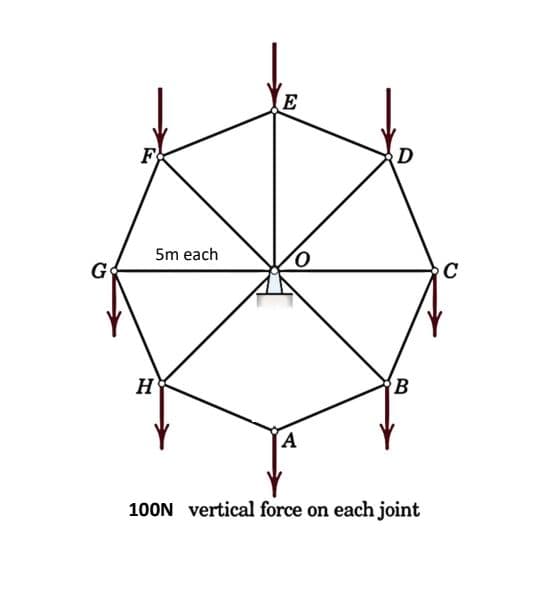
F 5m each E 0 D H B A 100N vertical force on each joint C


Q: Figure 1 shows a rigid body supported by a truss system, all elements are pinned at both ends. If a…
A:
Q: , Determine
A:
Q: Two parallel tangents 20 m. apart are to be connected by a reverse curve with equal radius at the…
A: reverse curve : A reverse curve is a segment of a highway or railroad route's horizontal alignment…
Q: Determine the Maximum positive moment (kN-m) in the beam shown Where: P = 83 kN; w = 12 kN/m; L1 = 2…
A: step 1-
Q: 2.) A 1060kN cube (3m each side) floats in a 1.8m depth of water which is on top of mercury layer.…
A: Size of cube and weight is given
Q: 10 k 6 m▬4 m→| 4 kN/m 8m
A:
Q: For the given figure below, write the shear and moment equation for each segment, draw the shear and…
A:
Q: Draw the shear and moment diagram
A:
Q: What are the functions of environment and energy engineering? What are their outputs?
A: There is very graet role of environmental engineering . By the means of environmental engineering we…
Q: For the load group and influence line shown, P₁ = 8 kips, P2 = 32 kips, P3 = 32 kips, a = 14', and b…
A:
Q: Linear Error of Closure Given a closed traverse with sum of south latitudes exceeds the sum of…
A: A closed traverse is given
Q: shown | = 61kN; P2 = 42kN; W1
A:
Q: A cyclist on a circular track of radius 800 ft is travelling at 27 fps. His sp the tangential…
A:
Q: What are the functions of structural engineering and what are their outputs?
A: Functions of structural engineering. Structural engineering is an important field of civil…
Q: In the overhanging beam show, determine P so that the moment over each support equals the moment at…
A: Determine P so that the moment over each support equals the moment at the midspan.
Q: Determine the force in member CD Determine the force in member DG Determine the force in member DH
A:
Q: The beam is loaded uniform deadload of 42 kN/m (including its own weight), and a uniform live load…
A:
Q: Determine the ultimate moment capacity of the beam with given properties below. d' = 70mm d = 430mm…
A:
Q: What is the span length L (in ft) of a uniformly loaded, simple beam of wide-flange cross section…
A:
Q: draw the shear & moment diagram for the frane 6 kN/m -6 kN 6m D 4m
A:
Q: OLL CLOL 3.0 m, and b-4.0 m In the following arrangement, determine the velocity of A at the instant…
A:
Q: 3. Determine the force in members AE, DE and AC of the truss shown. State whether each members is in…
A:
Q: A boat with mass 250 kg, including passengers, has an engine that produces a net horizontal force of…
A: We know that Force = mass * acceleration acceleration is in m/s^2 Mass=kg Force is in N
Q: The instrument was set at point A with HI of 12.35 m MSL. The top of the tower was sighted with…
A:
Q: Diameter of Orifice (mm) H (cm) Volume (Liters) Note: 1000 Liters = 1 m³ Time (seconds) Q actual…
A: Following is required answer :
Q: For the frame shown below, Determine the horizontal component of the reaction at A in kips Determine…
A:
Q: Q/1: A 10 m long vertical mast has a ball-and socket joint at A, and it is supported by two (2)…
A: Given Data: Force of 4 kn need to find tensions in T1 and T2
Q: A double angle tension member L5 x 3 x 1/4, is connected to a gusset plate with 7/8 inch diameter…
A: Answer Double angel 2L 5 x 3 x 14 Bolt diameter = 7/8 in Fy = 248.8 Mpa Fu = 400 Mpa Service Live…
Q: An extruded beam has the cross section shown. Determine the location e of the shear center O. 5 mm C…
A: From the given data: a = 30mm b= 45mm t1 = 4mm t2 = 5mm d = 70mm
Q: 35 aw the projections of this shape 25 20 20 A
A: GIVEN: TO FIND: Draw the projection of the given shape.
Q: Solve for the Beam reactions and draw the shear and moment diagram of the follo
A:
Q: Describe briefly how you transform a WBS into a Network Diagram
A: Given: To find: Draw network diagram
Q: Determine the required tension steel area of the T beam with given properties below. Width of flange…
A:
Q: What are the benefits of prototyping
A: The prototype provides the client with a total thought of how the site will look like in the…
Q: Dead load e (kip/ft) 0.2 0.2 0.2 0.2 0.2 0.2 0.2 0.2 load (kip/ft) 0.8 0.8 0.8 0.8 0.8 0.8 0.8 0.8…
A: Case 6 Deflection is not concerned Lrfd method
Q: A rectangular beam has a width of 260 mm and an overall depth of 470 mm. concrete cover is 60 mm…
A: Appreciate if there is detailed work with explanation and finds you helpful for ease of…
Q: Determine the forces in all members using method of joints. 7. 1kN 2kN 1kN 90° 300 12 m C 12 m 90°…
A: Determine the forces in all the members of given truss.
Q: Determine the maximum positive moment (lbs-ft) in th beam as shown. Where: L1 = 6.5ft; L2 = 3.8 ft;…
A:
Q: Draw the shear and moment diagram of the beam shown using the area method. 5 kN/m A C D 1m 3 B 1m 3m…
A:
Q: Question 3) 4m + 6m EA 1 77777 D rigid 5m 3 kN/m 1 1 I 1 +++ Figure-3 7m E 44444 2EA (2) B₁ I 1 The…
A:
Q: 3. Determine the force in members AB, AD and DE of the truss shown. State whether each members is in…
A:
Q: 50 kN/m
A:
Q: No. 3. A simply supported wood beam of rectangular cross section and span length, L = 1.2 m carries…
A: UDL on beam q = Area x Specific weight of beam =(0.14×0.24)×5.4…
Q: 1. The truck is moving along a 20 m span of beam. The front axle is 30 kN, the middle is 75 kN an…
A: P1 = 45KN P2 = 75KN P3 = 30KN
Q: Assume h=1.8 sec/veh. Pedestrian demand for all approaches is 120 per hour, pedestrian speed is 4…
A: Given: The critical lane volume is 120 per hour. The saturation volume for phase 1 is 2105 and 300…
Q: Alternative Wastewater Treatment Systems and Storm Sewers - Enumerate Alternative Wastewater…
A: waste water treatment system : A wastewater treatment system is a group of technologies that work…
Q: What factors influence the compressive strength of clay masonry?
A: There are several factors that can influence the compressive strength of clay masonry. 1. Water…
Q: The instrument was set at point A with HI of 12.35 m MSL. The top of the tower was sighted with…
A:
Q: A field is in the form of a regular triangle. If the true bearing of side AB is N 45°30'E, determine…
A:
Q: Beam ABC has fixed supports at A and C and at the midspan point B. It carries a uniform load of 48.6…
A: Figure is as shown with all details

This is a static of rigid bodies problem. Determine the forces in all members using method of joints.


Trending now
This is a popular solution!

Step by step
Solved in 3 steps with 3 images


- Q) Determine the elastic and plastic moment of resistance of the RC beam. The beam is a trapezoid in shape. B1 at top = 300mm, B2 at bottom = 500mm, total height = 600mm, height from top to the bottom of the steel reinforcement = 570mm, As = 1473mm^2, Fy=350MPa, Fcu=30MPa Solve this early I upvoteFind the value of maximum load P sothat the stresses in the frame illustrated willnot exceed 120MN/m2 in tension or 90MN/m2in compression.The bars of the pin-connected frame shownhave a section of 35mmx65mm each.A built-up beam made from fastening two channels to a wide flange section carriesloads` as shown. The fasteners are 12mm∅ bolts with allowable shear stress τ= 110 MPa. Forbearing, σb= 220MPa for single shear, and σb= 275 MPa for double shear. E=200 GPA. Fy=420MPa. Do not round off between solutions . Explain the Steps. a.) Determine the Moment of Inertia of the Sectionb.) Determine the Moment Capacity of the section if fb≤280MPa.c.) Determine the flexural stress at fiber 30 mm above Neutral Axis at distance 5 metersfrom the support at A.d.) Determine the maximum bending stress on the section.e.) Determine the maximum shearing stress at Neutral Axis.f.) Determine the horizontal shearing stress at 20 mm above the Neutral Axis.g.) Determine the horizontal shearing stress at 95 mm above the Neutral Axis.h.) Determine the spacing of the bolts.
- The cantilever beam is subjected to the load shown Below. Determine 1. the actual stresses acting at point A. (Hint: Tmas TIN EA). 2. IfG =30 GPa find the angle of twist at the free end of beam. 10 KNSteel Design Two channels having the given properties shown is placed at a distance of 300 mm to back and is properly connected by a pair of lacings as shown. Properties of one channel A = 5595 mm2 d = 305 mm x = 17mm Ix = 67.3 x 106 mm4 Iy = 2.12 x 106 mm4 rx = 19.3 mm Assume K = 1.0 Determine the safe axial load in kN, that the column section could carry. Unsupported height of column is 6m.A built-up beam made from fastening two channels to a wide flange section carriesloads` as shown. The fasteners are 12mm∅ bolts with allowable shear stress τ= 110 MPa. Forbearing, σb= 220MPa for single shear, and σb= 275 MPa for double shear. E=200 GPA. Fy=420MPa. Do not round off between solutions . Explain the Stepsa.) Determine the Moment of Inertia of the Sectionb.) Determine the Moment Capacity of the section if fb≤280MPa
- The overhanging beam shown supports the given ultimate load Wu= 5okN/m. The section is 300mm by 500mm rectangular beam having f'c=35MPa, fy=420 MPa, stirrups diameter = 10mm and concrete cover 40mm. a.) the area of steel reinforcement corresponding to rho max in mm2.b.) the location of the point of zero shear in the beam measured from the left support B in mm.c.) Calculate the maximum positive moment in the beam in kN.m.d.) Calculate the required reinforcement Asreqd corresponding to the maximum positive moment in mm2.e.) Calculate the depth of the compression block of the final positive moment section in mm.f.) Calculate the depth of the neutral axis of the final positive moment section in mm.g.) What is the ultimate moment capacity of the final positive moment section in kN.m.h.) Calculate the additional positive moment that can be imposed to the beam without exceeding the moment capacity of the final positive moment section in kN.m.An axially loaded column W360 x134 hasits weak axis braced at the third points.The overall length of the column 8 m. UseA 572 grade 50 Fy=345 MPa. The columnis pinned connected at both ends.Properties: rx = 155 mm, ry = 95 mm,A = 17,105 mm2 Determine the slenderness ratio withrespect to y-axis. Determine the slenderness ratio withrespect to x-axis. Determine the critical slendernessratio. What is the nominal compressivestrength of the steel column?34 - A support is a fixed, B support is a sliding joint. loads M= 30 kNm, P1= 12 kN, P2= 13 kN, q1= 6 kN ⁄ m, q2= 7 kN ⁄ m , spans are a= 2 m, b= 3 m. The support reactions in the beam whose loading condition is given in the figure will be found. Accordingly, Ax = ?A) 22.25B) 0C) None.D) 39.25E) 21/2
- A built-up beam made from fastening two channels to a wide flange section carriesloads as shown. The fasteners are 12mm∅ bolts with allowable shear stress τ= 110 MPa. Forbearing, σb= 220MPa for single shear, and σb= 275 MPa for double shear. E=200 GPA. Fy=420MPa. 1. Determine the Moment of Inertia of the Section2. Determine the Moment Capacity of the section if fb≤280MPa.3. Determine the flexural stress at fiber 30 mm above Neutral Axis at distance 5 metersfrom the support at A.A built-up beam made from fastening two channels to a wide flange section carriesloads` as shown. The fasteners are 12mm∅ bolts with allowable shear stress τ= 110 MPa. Forbearing, σb= 220MPa for single shear, and σb= 275 MPa for double shear. E=200 GPA. Fy=420MPa. 1. Determine the Moment of Inertia of the Section2. Determine the Moment Capacity of the section if fb≤280MPa.3. Determine the flexural stress at fiber 30 mm above Neutral Axis at distance 5 metersfrom the support at A.4. Determine the maximum bending stress on the section.5. Determine the maximum shearing stress at Neutral Axis.6. Determine the horizontal shearing stress at 20 mm above the Neutral Axis.7. Determine the horizontal shearing stress at 95 mm above the Neutral Axis.8. Determine the spacing of the bolts. Answer only the number 4-6. Thank you!A built-up beam made from fastening two channels to a wide flange section carriesloads` as shown. The fasteners are 12mm∅ bolts with allowable shear stress τ= 110 MPa. Forbearing, σb= 220MPa for single shear, and σb= 275 MPa for double shear. E=200 GPA. Fy=420MPa. 1. Determine the Moment of Inertia of the Section2. Determine the Moment Capacity of the section if fb≤280MPa.3. Determine the flexural stress at fiber 30 mm above Neutral Axis at distance 5 metersfrom the support at A.4. Determine the maximum bending stress on the section.5. Determine the maximum shearing stress at Neutral Axis.6. Determine the horizontal shearing stress at 20 mm above the Neutral Axis.7. Determine the horizontal shearing stress at 95 mm above the Neutral Axis.8. Determine the spacing of the bolts.