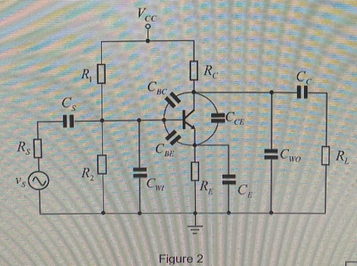
Figure 2 shows a typical BJT amplifier, with its parasitic capacitances displayed. The current gain of the transistor is B=150 and the voltage gain of the amplifier is Am =-125. The small signal resistances of the transistor are re =16 ohm and r0 = infinity, respectively. The values of resistors and capacitors in the figure are: R1 =80 kohm, R2 =20 Kohm, Rc = 2 Kohm, RE = 2 Kohm, Rs =50 W, RI=5 kohm, Cs=2 uF, Cc=2 uF, Ce =10 uF, Cbc =4 pF, Cbe = 10 pF, Cce =1 pF, Cwi = 4 pF, CWO = 9 pF, and Vcc = 20 V. a) Sketch a simplified circuit diagram of Figure 2 for high frequency analysis. b) Using the concept of "Miller effect capacitance", calculate the input and Output Miller effect capacitances of Figure 2, respectively. C) Determine the upper cut-off frequency of Figure 2 that is imposed by its input network only. d) Explain briefly the possible ways to increase the upper cut-off frequencv of this amplifier.
Figure 2 shows a typical BJT amplifier, with its parasitic capacitances displayed. The current gain of the transistor is B=150 and the voltage gain of the amplifier is Am =-125. The small signal resistances of the transistor are re =16 ohm and r0 = infinity, respectively. The values of resistors and capacitors in the figure are: R1 =80 kohm, R2 =20 Kohm, Rc = 2 Kohm, RE = 2 Kohm, Rs =50 W, RI=5 kohm, Cs=2 uF, Cc=2 uF, Ce =10 uF, Cbc =4 pF, Cbe = 10 pF, Cce =1 pF, Cwi = 4 pF, CWO = 9 pF, and Vcc = 20 V. a) Sketch a simplified circuit diagram of Figure 2 for high frequency analysis. b) Using the concept of "Miller effect capacitance", calculate the input and Output Miller effect capacitances of Figure 2, respectively. C) Determine the upper cut-off frequency of Figure 2 that is imposed by its input network only. d) Explain briefly the possible ways to increase the upper cut-off frequencv of this amplifier.

Introductory Circuit Analysis (13th Edition)
13th Edition
ISBN:9780133923605
Author:Robert L. Boylestad
Publisher:Robert L. Boylestad
Chapter1: Introduction
Section: Chapter Questions
Problem 1P: Visit your local library (at school or home) and describe the extent to which it provides literature...

Related questions

Question
Figure 2 shows a typical BJT amplifier, with its parasitic capacitances displayed. The current gain of the transistor is B=150 and the voltage gain of the amplifier is Am =-125. The small signal resistances of the transistor are re =16 ohm and r0 = infinity, respectively. The values of resistors and capacitors in the figure are:
R1 =80 kohm, R2 =20 Kohm, Rc = 2 Kohm, RE = 2 Kohm, Rs =50 W, RI=5 kohm, Cs=2 uF, Cc=2 uF, Ce
=10 uF, Cbc =4 pF, Cbe = 10 pF, Cce =1 pF, Cwi = 4 pF, CWO = 9 pF, and Vcc = 20 V.
a) Sketch a simplified circuit diagram of Figure 2 for high frequency analysis.
b) Using the concept of "Miller effect capacitance", calculate the input and Output Miller effect
capacitances of Figure 2, respectively.
C) Determine the upper cut-off frequency of Figure 2 that is imposed by its input network only.
d) Explain briefly the possible ways to increase the upper cut-off frequencv of this amplifier.
Transcribed Image Text:Vec
R,
R
R.
Figure 2
Expert Solution
This question has been solved!
Explore an expertly crafted, step-by-step solution for a thorough understanding of key concepts.

Step by step
Solved in 4 steps with 2 images

Knowledge Booster


Learn more about
Need a deep-dive on the concept behind this application? Look no further. Learn more about this topic, electrical-engineering and related others by exploring similar questions and additional content below.Recommended textbooks for you
Introductory Circuit Analysis (13th Edition)
Electrical Engineering
ISBN:
9780133923605
Author:
Robert L. Boylestad
Publisher:
PEARSON

Delmar's Standard Textbook Of Electricity
Electrical Engineering
ISBN:
9781337900348
Author:
Stephen L. Herman
Publisher:
Cengage Learning

Programmable Logic Controllers
Electrical Engineering
ISBN:
9780073373843
Author:
Frank D. Petruzella
Publisher:
McGraw-Hill Education
Introductory Circuit Analysis (13th Edition)
Electrical Engineering
ISBN:
9780133923605
Author:
Robert L. Boylestad
Publisher:
PEARSON
Delmar's Standard Textbook Of Electricity
Electrical Engineering
ISBN:
9781337900348
Author:
Stephen L. Herman
Publisher:
Cengage Learning
Programmable Logic Controllers
Electrical Engineering
ISBN:
9780073373843
Author:
Frank D. Petruzella
Publisher:
McGraw-Hill Education

Fundamentals of Electric Circuits
Electrical Engineering
ISBN:
9780078028229
Author:
Charles K Alexander, Matthew Sadiku
Publisher:
McGraw-Hill Education

Electric Circuits. (11th Edition)
Electrical Engineering
ISBN:
9780134746968
Author:
James W. Nilsson, Susan Riedel
Publisher:
PEARSON

Engineering Electromagnetics
Electrical Engineering
ISBN:
9780078028151
Author:
Hayt, William H. (william Hart), Jr, BUCK, John A.
Publisher:
Mcgraw-hill Education,