Figure Qla. R4 ww R2 R1 R3 e Figure Qla RI, R2, R3 and R4 are resistors and Cl and C2 are capacitors. Assume both op-amps are ideal and their input/output voltages are ei, e and eo, as shown in the Figure. Using the impedance approach: obtain the transfer function for each op-amp, i.e. E(s)/E:(s) and E(s)/E(s). (i) (ii) hence obtain the complete transfer function for the system, i.e. E(s)/Ei(s). (iii) Determine D(s) = E.(s)/E:(s) when RI = R2 = R3 R4 12 and Ci =1 F, C2 2 F. (b) Consider the closed-loop control system shown in Figure Qlb. Σ K.D(s) (s+2) Figure Qlb K is the gain and D(s) is the transfer function obtained in part (a)-iii. (i) Plot open loop zeros and poles for the above system in the s-plane. ". Determine whether the point (-1+j) is a closed loop pole for any value of K, by considering the angle criterion at this point. (ii)
Figure Qla. R4 ww R2 R1 R3 e Figure Qla RI, R2, R3 and R4 are resistors and Cl and C2 are capacitors. Assume both op-amps are ideal and their input/output voltages are ei, e and eo, as shown in the Figure. Using the impedance approach: obtain the transfer function for each op-amp, i.e. E(s)/E:(s) and E(s)/E(s). (i) (ii) hence obtain the complete transfer function for the system, i.e. E(s)/Ei(s). (iii) Determine D(s) = E.(s)/E:(s) when RI = R2 = R3 R4 12 and Ci =1 F, C2 2 F. (b) Consider the closed-loop control system shown in Figure Qlb. Σ K.D(s) (s+2) Figure Qlb K is the gain and D(s) is the transfer function obtained in part (a)-iii. (i) Plot open loop zeros and poles for the above system in the s-plane. ". Determine whether the point (-1+j) is a closed loop pole for any value of K, by considering the angle criterion at this point. (ii)

Delmar's Standard Textbook Of Electricity
7th Edition
ISBN:9781337900348
Author:Stephen L. Herman
Publisher:Stephen L. Herman
Chapter18: Resistive-inductive Parallel Circuits
Section: Chapter Questions
Problem 13PP: In an R-L parallel circuit, IT=1.25 amps, R=1.2k, and XL=1k. Find IR

Related questions

Question
Transcribed Image Text:An operational-amplifier circuit that may be used as a controller is shown in
Figure Qla.
-1
(а)
R4
ww
R2
ww
ww
R3
R1
Figure Qla
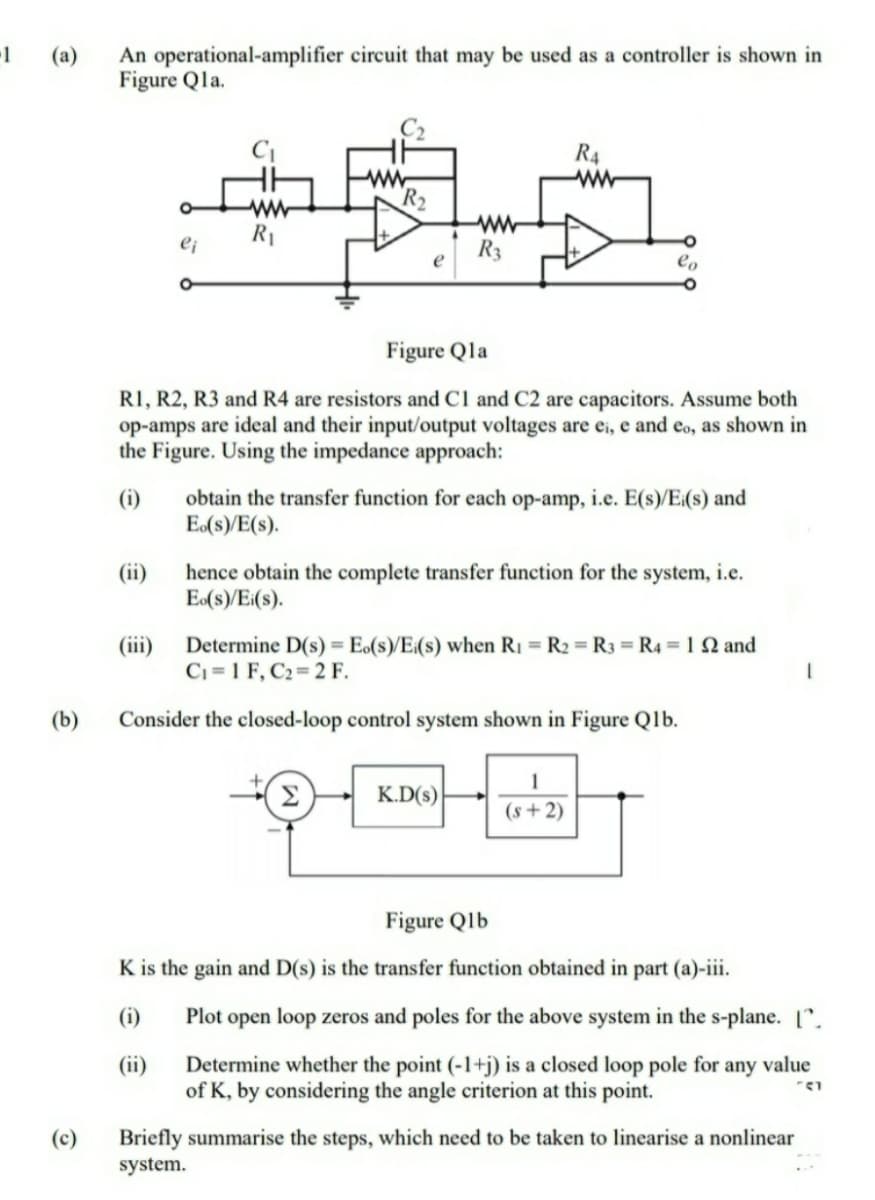
R1, R2, R3 and R4 are resistors and Cl and C2 are capacitors. Assume both
op-amps are ideal and their input/output voltages are ei, e and eo, as shown in
the Figure. Using the impedance approach:
obtain the transfer function for each op-amp, i.e. E(s)/E:(s) and
E(s)/E(s).
(i)
hence obtain the complete transfer function for the system, i.e.
E(s)/Ei(s).
(ii)
(iii)
Determine D(s) = E.(s)/E:(s) when R1 = R2 = R3 = R4 = 1 N and
C1 =1 F, C2 2 F.
(b)
Consider the closed-loop control system shown in Figure Qlb.
1
Σ
K.D(s)
(s + 2)
Figure Qlb
K is the gain and D(s) is the transfer function obtained in part (a)-iii.
(i)
Plot open loop zeros and poles for the above system in the s-plane. [".
Determine whether the point (-1+j) is a closed loop pole for any value
of K, by considering the angle criterion at this point.
(ii)
(c)
Briefly summarise the steps, which need to be taken to linearise a nonlinear
system.
Expert Solution
This question has been solved!
Explore an expertly crafted, step-by-step solution for a thorough understanding of key concepts.

Step by step
Solved in 4 steps with 3 images

Knowledge Booster


Learn more about
Need a deep-dive on the concept behind this application? Look no further. Learn more about this topic, electrical-engineering and related others by exploring similar questions and additional content below.Recommended textbooks for you
Delmar's Standard Textbook Of Electricity
Electrical Engineering
ISBN:
9781337900348
Author:
Stephen L. Herman
Publisher:
Cengage Learning
Delmar's Standard Textbook Of Electricity
Electrical Engineering
ISBN:
9781337900348
Author:
Stephen L. Herman
Publisher:
Cengage Learning