An operational amplifier (op-amp) is shown in Figure Q2(a). Given R; = 15 k2, Rf = 100 k2 and supply voltages as ±20 V. Assume that the comparator output has a loss of 1V. (i) Determine the upper trigger point (UTP) and lower trigger point (LTP) values. Sketch the output voltage waveform with respect to its input waveform by assuming that the input is a sinusoidal signal having peak-to-peak voltage, VPp = 20 V. (ii) (iii) Modify the circuit to provide trigger points that are not equal in magnitude (UTP # LTP). Re-sketch the schematic for the non-inverting circuit.
An operational amplifier (op-amp) is shown in Figure Q2(a). Given R; = 15 k2, Rf = 100 k2 and supply voltages as ±20 V. Assume that the comparator output has a loss of 1V. (i) Determine the upper trigger point (UTP) and lower trigger point (LTP) values. Sketch the output voltage waveform with respect to its input waveform by assuming that the input is a sinusoidal signal having peak-to-peak voltage, VPp = 20 V. (ii) (iii) Modify the circuit to provide trigger points that are not equal in magnitude (UTP # LTP). Re-sketch the schematic for the non-inverting circuit.

Power System Analysis and Design (MindTap Course List)
6th Edition
ISBN:9781305632134
Author:J. Duncan Glover, Thomas Overbye, Mulukutla S. Sarma
Publisher:J. Duncan Glover, Thomas Overbye, Mulukutla S. Sarma
Chapter12: Power System Controls
Section: Chapter Questions
Problem 12.3P

Related questions

Question
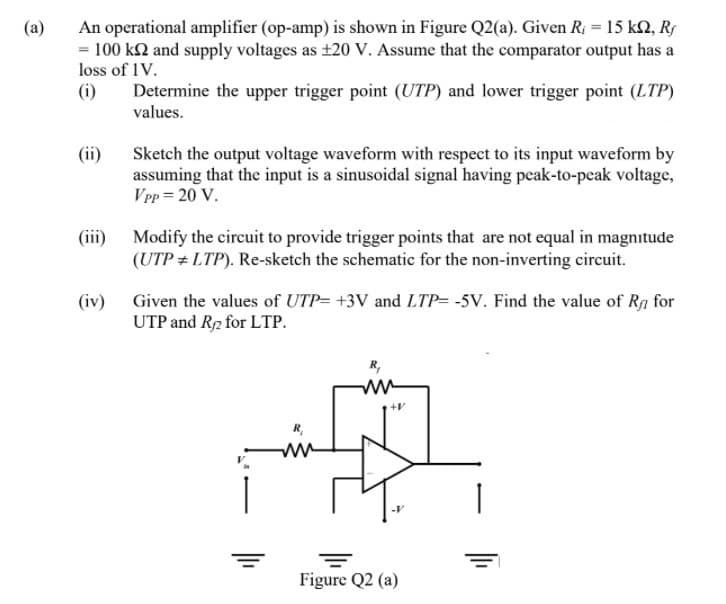
Transcribed Image Text:An operational amplifier (op-amp) is shown in Figure Q2(a). Given R; = 15 k2, Rs
= 100 k2 and supply voltages as ±20 V. Assume that the comparator output has a
loss of 1V.
(i)
(a)
Determine the upper trigger point (UTP) and lower trigger point (LTP)
values.
(ii)
Sketch the output voltage waveform with respect to its input waveform by
assuming that the input is a sinusoidal signal having peak-to-peak voltage,
VPp = 20 V.
(iii) Modify the circuit to provide trigger points that are not equal in magnitude
(UTP + LTP). Re-sketch the schematic for the non-inverting circuit.
(iv) Given the values of UTP= +3V and LTP= -5V. Find the value of Rg for
UTP and R2 for LTP.
R,
+V
ww
Figure Q2 (a)
Expert Solution
This question has been solved!
Explore an expertly crafted, step-by-step solution for a thorough understanding of key concepts.

Step by step
Solved in 3 steps with 2 images

Knowledge Booster


Learn more about
Need a deep-dive on the concept behind this application? Look no further. Learn more about this topic, electrical-engineering and related others by exploring similar questions and additional content below.Recommended textbooks for you
Power System Analysis and Design (MindTap Course …
Electrical Engineering
ISBN:
9781305632134
Author:
J. Duncan Glover, Thomas Overbye, Mulukutla S. Sarma
Publisher:
Cengage Learning
Power System Analysis and Design (MindTap Course …
Electrical Engineering
ISBN:
9781305632134
Author:
J. Duncan Glover, Thomas Overbye, Mulukutla S. Sarma
Publisher:
Cengage Learning