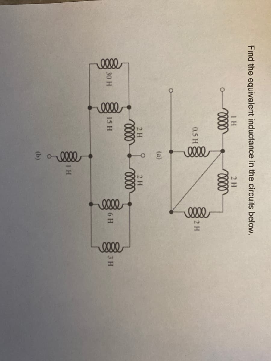
Find the equivalent inductance in the circuits below. 1 H 2 H 0.5 H 2 H (a) 2 H 2 H 30 H 15 H 6 H 3 H (b)


Q: In the following circuit, if L, = 10 H, then the energy stored in the inductor is: %3D 22 ww "C = 2…
A: Find the energy in the inductor if the inductor L= 10H Inductor act as short circuit after long time…
Q: 3 μ 6 µF a E = 36V 4 μF 24 µF 12 µF Consider the circuit shown in the figure. What is the charge for…
A:
Q: The current in the capacitor is 0 for t<0 and 3 cos 50,000t A for t≥0. Find (a) v(t); (b) the…
A: a) Calculating voltage across capacitor
Q: 15. A 10 µF capacitor is charged to 120 V and then discharged through a 1.5MN resistor. Find how…
A:
Q: (a) The circuit shown below has the following parameters: C1 = 17 µF, C2 = 8 µF, C3 = 5 µuF and V =…
A: The capacitor is a charge storing electrical element. its works on the electrostatic principle.If a…
Q: The circuit shown below contains seven capacitors, each having capacitance C. The source voltage is…
A:
Q: If the current through a 500 mF capacitor is given as i(t) = 2t +3, the voltage across the capacitor…
A:
Q: H1) For the circuit of Figure below, compute the energy stored in the 10 mH inductor at t = 100 ms.…
A: The 5u0(t) source will be active only for t>0 and thus it will be equal to 5A. We will do source…
Q: The circuit shown below has the following parameters: C1 = 15 µF, C2 = 8 µF, C3 = 11 µF and V = 175…
A: What is value of total capacitor and charge on each capacitor. Capacitor are connet in Series…
Q: 1,3 ka my 7k2 マエL 3Vc 9mH 1,1 k-2 Ve 18 1,7K2
A: Given the circuit is in steady state
Q: For the following circuit, assume that it has been in this state for a very long time. Dete the…
A: Given that Electrical network as follows
Q: The circuit shown below has the following parameters: C1 = 5 µF, C2 = 2 µF, C3 = 17 µF and V = 160…
A: According to the question we have to find the value of the total capacitor and charge on each…
Q: SITUATION NO. 10 - The voltage across the 1 H inductor is 3e^(-t) V. Assume i(0) = 5 20. Find the…
A:
Q: During the charging process of the RC- circuit, the current changes as a function of time as shown.…
A: " Since you have asked multiple questions, we will solve the first question for you. If you want an…
Q: Four capacitors are connected as shown in the figure below. (Let C = 12.0 µF.) C 3.00 μF th. 20.0 µF…
A:
Q: Find the equivalent inductance of the circuit shown in Fig. 6.31. Leg 4 H m m 8 H 7 H 20 H m m 10 H…
A: Given circuit,
Q: 400 pF 100 pF 400 µF +1.5V 300 µF 100µF
A: According to the question we have to find the value of charge on the 300 μF capacitor.
Q: Calculate the equivalent inductor (mH) for the circuit.L1= 7mH, L2 = 5mH, and L3 = 5mH. %3D L2 L1…
A:
Q: Three inductances are connected as shown in Fig. What is the equivalent inductance? 0.1 H 0.3 H 0.5…
A: Given circuit:
Q: How large must inductor Lx be in order to provide a total inductance of 2.5 H in this network of…
A:
Q: H.W.: A voltage source, vs = 20u(t) V, is in series with a 200 Q resistor and a 4 H inductor. Find…
A:
Q: If the current through a 100 mH inductor is given as i(t) = 2t +3, the voltage across the inductor…
A:
Q: 13 i) (A) I(s) If the current flowing through a 75 mH inductor has the waveform shown, what is the…
A: We need to find out inductor voltage for given current waveform .
Q: A 5-H inductor changes its current by 3 A in 0.2 s, the voltage produced at the :terminals of the…
A: Inductor(L)=5H Change in current (dI)=3A Change in time(dt)=0.2sec
Q: R, R2 R3 Vs + ww
A:
Q: 6.2.2 The voltage across a capacitor with 60 UF capacitance has energy function 14. cos“ (a · t) J,…
A: The solution is given below
Q: 3. Find the equivalent capacitance between points A and B. 8 µF A 7 µF 5 µF 1 μΕ 8 µF 20 μ . 3 µF 10…
A: Redraw the above circuit and represent the nodes with the same potential.
Q: 3µF В A 2µF 3µF 3µF 4µF In the circuit given in the figure, in which of the following options is the…
A: In the question, Find the equivalent capacitance across the terminal a and b. In the circuit…
Q: Three inductances are connected as shown in Fig. What is the equivalent inductance? 0.1 H 0.3 H 0.5H…
A: Given data, Circuit diagram is given as,
Q: Determine the value of the intial and final energy of the 3 H inductor whose current for t> 0 is…
A:
Q: Four capacitors are connected as shown in the figure below. (Let C = 20.0 µF.) C 3.00 μΕ Hh. 20.0 μF…
A:
Q: 6. Obtain the energy stored in each capacitor in the figure as shown under dc conditions. 2 mF 2 k2…
A: Here, we have given a electrical network. This network consists of series and parallel combination…
Q: What is the inductor current at t= 200 µs the circuit shown? 50 mH 1 k2 X t=0 5 mA, 2502 İL = _ mA
A: The given circuit is
Q: Apply combinatorial techniques as appropriate to obtain a value for the equivalent inductance Leg as…
A:
Q: For the given voltage across a 3 H inductor, plot the current and power waveforms assuming an…
A: It had been given that the initial inductor current is zero. The inductor current equation has been…
Q: 6. The voltage across a 2 (uF) capacitor is shown below. Sketch the voltage across the capacitor,…
A: Part (a) Write the expression for voltage across the capacitor,
Q: 3. The current through an inductor with inductance of 1mH is given as i(t)= 0.010 sin 10°t A. What…
A:
Q: 50µF 60μF Сед 70µF : 20μF :120μF
A: Find the equivalent capacitance for the given circuit?
Q: 3. Find the equivalent capacitance of the group of capacitors shown in the circuit below. 15.00 μF…
A: Given,
Q: For the given circuit, find the current, voltage, power and energy of the inductor as a function of…
A: As per company guidelines, only the first 3 parts will be solved. If other parts are needed, please…
Q: A positive constant voltage across an inductor implies zero current through it. Select one: O True O…
A:
Q: A 2.5-µH inductor has a resistance of 23 V. At a frequency of 35 MHz, find its Q. (round-off your…
A:
Q: 3. EQUIVALENT CAPACITANCE. Solve for the equivalent capacitance. 2µF 2µF 2µF 3µF 3µF 6µF 3µF 6µF b…
A:
Q: The circuit shown below has the following parameters: C1 = 9 µF, C2 = 2 µF, C3 = 9 µF and V = 180 V.…
A: Given : Capacitor is a electrical element which is used to store the charges in the form of…
Q: The following circuit has an equivalent capacitance of 16 µF. Find a) The total energy stored in…
A: Capacitance: Capacitance of a capacitor is defined as the ratio of the amount of charge stored to…
Q: Assume that the initial energy stored in the inductor of the provided figure is zero and that L1 =…
A: When two inductors are connected in parallel there equivalent is given as follows Leq = L1.L2/…
Q: For the circuit shown in the following figure, if L= 28 H, Vo=13 V, and R= 28 Q, answer the…
A: In the circuit given data is- L=28 HV∘=13 VR=28 Ω In Laplace domain-…
Q: Determine the charge stored on a 3 µF capacitor if the capacitor's voltage is 6 V. а. 18 иF b. 19 µF…
A:
Q: 13 i(1) (A) I(s) 10 If the current flowing through a 75 mH inductor has the waveform shown, what is…
A: In this question, Current waveform in the inductor is given. Find the voltage across the inductor…


Trending now
This is a popular solution!

Step by step
Solved in 3 steps with 2 images

- Assume that the current flow through the resistor, IR, is 15 A; the current flow through the inductor, IL is 36 A; and the circuit has an apparent power of 10,803 VA. The frequency of the AC voltage is 60 Hz. ET ER EL IT IR15A IL36A Z R XL VA10,803 P VARSL PF LInductive Circuits Fill in all the missing values. Refer to the following formulas: XL=2fLL=XL2ff=XL2L Inductance (H) Frequency (Hz) Inductive Reactance ( ) 1.2 60 0.085 213.628 1000 4712.389 0.65 600 3.6 678.584 25 411.459 0.5 60 0.85 6408.849 20 201.062 0.45 400 4.8 2412.743 1000 40.841Three capacitors having capacitance values of 20F,40F, and 50F are connected in parallel to a 60 - Hz power line. An ammeter indicates a circuit current of 8.6 amperes. How much current is flowing through the 40F capacitor?
- Assume that the voltage drop across the resistor, ER, is 78 V, that the voltage drop across the inductor, EL, is 104 V, and the circuit has a total impedance, Z, of 20 . The frequency of the AC voltage is 60 Hz. ETITZ20VAPFER78VIRRPEL104VILXLVARsLLAn AC circuit contains a 24 resistor, a 15.9-mH inductor, and a 13.3F capacitor connected in parallel. The circuit is connected to a 240-V, 400-Hz power supply. Find the following values. XL=XC=IR=AIL=AIC=AP=WVARsL=VARsC=IT=AVA=PF=%=You are a journeyman electrician working in an industrial plant. Your task is to connect an inductor to a 480-V, 60-Hz line. To determine the proper conductor and fuse size for this installation, you need to know the amount of current the inductor will draw from the line. The nameplate on the inductor indicates that it has an inductance of 0.1 H. An ohmmeter reveals that it has a wire resistance of 10 . How much current should this inductor draw when connected to the line?
- You are an electrician working in an industrial plant. You discover that the problem with a certain machine is a defective capacitor. The capacitor is connected to a 240-volt AC circuit. The information on the capacitor reveals that it has a capacitance value of 10 mF and a voltage rating of 240 VAC. The only 10-mF AC capacitor in the storeroom is marked with a voltage rating of 350 WVDC. Can this capacitor be used to replace the defective capacitor? Explain your answer.Find the equivalent inductance (???) in the circuit.Q1 (True/False): A) The current through the capacitor is inversely proportional to the derivative of the voltage across it: Is it true or false? B) In a typical electronic circuit the capacitor blocks DC and couplest he AC to the next stage of the circuit: Is it true or false? C) The more the value of the stray capacitance , the better it is: Is it true or false?
- A pure inductance of L = 120 mH is connected to a V = 102 V, 50 Hz supply. The current taken by the inductor is given byThe voltage across a 10-μ H inductance is given by v( t )=5 sin( 10 6 t ) V. The initial current is i( 0 )=−0.5 A. Find expressions for the current, power, and stored energy for t>0. Sketch the waveforms to scale versus timeDescribe the behavior of the following circuit under the following scenario: (1) Begin with switch S1 open, (2) close switch S1 long enough till the voltage across the inductor is almost zero, and then (3) open switch S1 for a long time beginning at time t = 0.