The circuit shown below has the following parameters: C1 = 9 µF, C2 = 2 µF, C3 = 9 µF and V = 180 V. %3D Determine: (i) Total Capacitance (ii) Charge on each capacitance in µC . C2 C, C3
The circuit shown below has the following parameters: C1 = 9 µF, C2 = 2 µF, C3 = 9 µF and V = 180 V. %3D Determine: (i) Total Capacitance (ii) Charge on each capacitance in µC . C2 C, C3

Delmar's Standard Textbook Of Electricity
7th Edition
ISBN:9781337900348
Author:Stephen L. Herman
Publisher:Stephen L. Herman
Chapter19: Capacitors
Section: Chapter Questions
Problem 2PP: Two capacitors having values of 80 F and 60 F are connected in series. What is the total...

Related questions

Concept explainers
KVL and KCL
KVL stands for Kirchhoff voltage law. KVL states that the total voltage drops around the loop in any closed electric circuit is equal to the sum of total voltage drop in the same closed loop.
Sign Convention
Science and technology incorporate some ideas and techniques of their own to understand a system skilfully and easily. These techniques are called conventions. For example: Sign conventions of mirrors are used to understand the phenomenon of reflection and refraction in an easier way.
Question
23
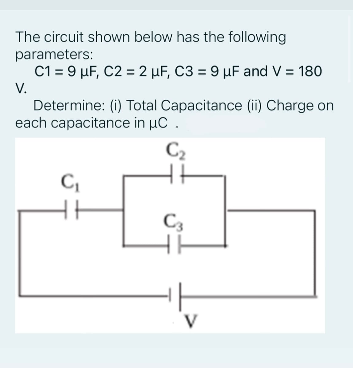
Transcribed Image Text:The circuit shown below has the following
parameters:
C1 = 9 µF, C2 = 2 µF, C3 = 9 µF and V = 180
%3D
V.
Determine: (i) Total Capacitance (ii) Charge on
each capacitance in µC .
C2
C,
C3
V
Expert Solution
This question has been solved!
Explore an expertly crafted, step-by-step solution for a thorough understanding of key concepts.

Step by step
Solved in 4 steps with 3 images

Knowledge Booster


Learn more about
Need a deep-dive on the concept behind this application? Look no further. Learn more about this topic, electrical-engineering and related others by exploring similar questions and additional content below.Recommended textbooks for you
Delmar's Standard Textbook Of Electricity
Electrical Engineering
ISBN:
9781337900348
Author:
Stephen L. Herman
Publisher:
Cengage Learning

Electricity for Refrigeration, Heating, and Air C…
Mechanical Engineering
ISBN:
9781337399128
Author:
Russell E. Smith
Publisher:
Cengage Learning
Delmar's Standard Textbook Of Electricity
Electrical Engineering
ISBN:
9781337900348
Author:
Stephen L. Herman
Publisher:
Cengage Learning
Electricity for Refrigeration, Heating, and Air C…
Mechanical Engineering
ISBN:
9781337399128
Author:
Russell E. Smith
Publisher:
Cengage Learning