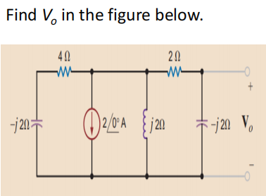
Find V in the figure below.


Q: 3.13. Consider the system shown in Figure 3.75. As- sume that the average value of m (t) is zero and…
A: As asked in the question, we need to solve problem 3.13. Since you have posted a question with…
Q: Fig. P3.4 shows an electromagnet system for lifting a section of steel channel. The coil has 600…
A: The diagram of the electromagnetic system is shown below,
Q: Question #5 y(t) Answer: 1.4 1.2 0.8 0.6 0.4 0.2 0 1 0 5 t (sec) A periodic signal has the waveform…
A:
Q: 1. The switch in the circuit shown in Figure below has been closed for a long time before it is…
A:
Q: Discuss the importance of VRM (Voltage Regulator Module) and its impact on CPU performance and…
A: we need to discuss:the importance of VRM (Voltage Regulator Module) and its impact on CPU…
Q: what is the implementation of the load flow analysis
A: Load flow analysis, also known as power flow analysis, is a crucial component of electrical power…
Q: What is the period of a voltage source described as v(t) = 7.2 cos (243 t - 13°) mV? Please enter…
A: The equation given is in the form: v(t) = Vmcos(ωt+ϕ) Where:Vm is the maximum voltage (amplitude)…
Q: 8 mA ↑ M 4000x + 3kQ 2 mA 2 k m : 6 kQ www IRQ ob
A:
Q: 4.19 a) Use the node-voltage method to find Vo for the circuit in Fig. P4.19. b) Find the total…
A: The circuit diagram,
Q: A discrete-time LTI system is defined by its impulse response h[n] by h[n] = n for 2 ≤n ≤ 1 *…
A: for the given discrete time LTI system with impulse response h(n) for input x(n) it is asked to find…
Q: Can you please explain the steps on how to solve for equations lll, IV, and V to get the current…
A: The question is about finding currents.
Q: Get G₁₂ G₁3
A:
Q: Tesistol SMS after the switch has been openica. 2. The switch in the circuit shown in Figure 2 has…
A: We need to find out the initial voltage and voltage across capacitor and energy for capacitor in the…
Q: Find the transfer function from force u to posi- tion y y k F m₂ Y( w m₂ u Frictionless surface
A: Given that , Transfer function
Q: A coaxial capacitor of length 1 = 6 cm uses an insulating dielectric material with = 9. The radii of…
A:
Q: Let V₁-10V, R₁-202, R₂-202, R3-302 and R4-12 in the circuit of Fig. 5_4. Find the Thevenin (Vth.…
A:
Q: Using superposition, determine the current through the inductance XL for the network below I = 0.3…
A: In this question, we need to determine the current through the inductance XL using the…
Q: 5. A 3-4, 400 V, 12 KVA induction motor with a power factor of 70% is connected across a 3-0, 400 V,…
A:
Q: A coil consists of 100 turns of wire wrapped around a square frame of sides 0.2 m. The coil is…
A: Number of turns N = 100.Side length a = 0.2 m.Area Magnetic field
Q: 1-9. A wire is shown in Figure Pl-6 that is carrying 2.0 A in the presence field. Calculate the…
A: Wire shown in figure:Magnetic field,, ,Length of the wire, Current,
Q: Find the power for the 4 resistor and each of the voltage sources. 8V 1Ω Μ 3Ω 4Ω Μ 3V 6Ω 5Ω 3Ω ww 1Α…
A: Solve for power at 4 ohm resistor and atvoltage sources. Using mesh current analysis.Let us define…
Q: Is this signal periodic or aperiodic? Please show working.
A: Given:a signal, ,To find:whether the given signal is periodic or aperiodic?
Q: The voltages va, vb, and vc in below Figure are the node voltages corresponding to nodes a, b, and…
A: GivenThe DC circuit diagram with dependent current source is given as,Here,, and To find Determine…
Q: BC:5.2 In the flow diagram shown in Fig. 2, the blocks with the "D" represent a one-step time delay.…
A: Block diagram is given as,We need to find the difference equation in the following…
Q: Given the circuit below, find the output voltage vout measured across the resistor. You are told…
A: Given circuit is,Asked to find the magnitude of output voltage?
Q: nap 19ismlov A a) Find the current i, in the circuit in Fig. P4.61 using a sequence of appropriate…
A: Given Data:A DC resistive circuit with,Voltage source Current source To Find:The value of the output…
Q: The voltages v1, v2, v3, and v4 are the node voltages corresponding to nodes 1, 2, 3, and 4 in the…
A: In the given circuit the value of unknown node voltages needs to be calculated and the same can be…
Q: Vx 2000 Vx + 4 ΚΩ 2 mA (+1) 2 ΚΩ 3V 6 ΚΩ A Vo B
A: Note: Since you asked multiple questions, according to Bartleby guidelines we can answer only the…
Q: b) Find the secondary voltage of an iron-core transformer if the applied voltage is 20 V, and Np=60…
A: Number of turns in primary, Number of turns in secondary,The primary voltage,
Q: Explore the concept of motherboard power delivery systems, including voltage regulation modules…
A: The motherboard's power delivery system plays a critical role in supplying power to the CPU and…
Q: Obtain the Thevenin equivalent seen at terminals of the circuit given below, where R₁ = 4.3 0 and R₂…
A: In this question, we need to determine the thevenin equivalent circuit across the terminals a and b.…
Q: system are given below: i(t) (input) (output) i(t) i(t) i(t) + iz(t) dv(t) i₂(t) = C dt di₁(t) v(t)=…
A: For the given RLC circuit, we need to determine:variation in resistor values at steady-state, and…
Q: Determine Vo, for the circuits shown below. OPAMP is ideal.
A:
Q: Max Power transper bov (+) Sr Tor RL 212 52 100 محر 2) Fond R₂ that results on max power transfer.…
A: We need to find out the value of load resistor and maximum power across load resistance for given…
Q: Given the signal flow graph: G₁(s) R(s) Answer: G₂(s) V4(S) Answer: H₁(s) Gg(s) G3(s) V3(s) V6(s)…
A: The signal flow graph (SFG) is given byWe need to findThe determinant of whole SFG, Δ.The numerator…
Q: In the circuit of Fig. 5_2, let V,-6 V, 1₂-3 A, R₁-22, R₂=202, R₁=102, R₁-192. Which of the…
A: GivenThe DC circuit diagram is given by,Here,, , , , To findThe current value for different…
Q: Demonstrate this equation for the following circuit: Circuit : additive amplifier Demonstrate that V…
A: The given circuit isWe need to find the expression for the voltage Vs in terms of Ve1 and Ve2 if R1…
Q: Discuss Microchip's contributions to the field of analog and mixed-signal integrated circuits (ICs).…
A: Microchips Techno;pgy Inc. is a well known semiconductor manufacturer that has made significant…
Q: Branch-current Analysis ((a)) Construct the network of Fig. 14.1 and insert the measured values of…
A: Nodal analysis is a widely used technique in electrical circuit analysis, specifically for solving…
Q: the output is the voltage over the inductor find an R value such that the amplitude of Vout in the…
A: In this question, we need to determine the value of R. We solve this problem using the voltage…
Q: system are given below: (input) i(t) = 2u(t) (output) v(oo) (in steady-state) can take any value…
A: For the given RLC circuit, we need to determine:variation in resistor values at steady-state, and…
Q: 4. A balanced 30 wye load is connected across a 115 volts 30, 3-wire, an-bn-cn source. If the…
A: In this question, we need to determine power triangle of the star connected load. We know, apparent…
Q: 5. Determine the electric current passing through the diode in the circuit illustrated in Figure…
A:
Q: - To find a Io, use a Source Transformation ww 4 ΚΩ 2 ΚΩ Σ 2 mA 6V • 2 ΚΩ Το 6 ΚΩ +)3v
A: In this question, we need to determine the value of current Io using the source transformation.
Q: · ● The CPU inside your computer has an operating frequency of 452.099Hertz The transistors in your…
A: In this question, we need to determine the energy by CPU in 1 hour. We know, Power P= VIEnergy…
Q: For the circuit shown in Figure, find the input-output differential equation. (1) 8 H ele 492 F=40e
A: The given circuit isWe need to find the input-output differential equation.
Q: 9. Referring to circuit below: a) write the KCL equations of nodes: c, d, e, g a C I3 4 II 20 8V,…
A: Given network is , Determine KCL equations at…
Q: For the circuit shown below, determine: The Thevenin's equivalent voltage Eth and the Thevenin's…
A:
Q: Discuss the role of IoT in optimizing energy consumption in smart cities
A: IoT (Internet of Things) plays a crucial role in optimizing energy consumption in smart cities by…
Q: Find the potential difference across each resistor in the figure below. (R₁ = 5.402, R₂ = 3.80 2, R₂…
A: We need to find out voltage across each resistor for given circuit.

Step by step
Solved in 3 steps with 3 images


- The circuit is connected to a 400-Hz line with an applied voltage of 35.678 V. The resistor has a true power of 14.4 W. and there are 12.96 inductive VARs and 28.8 capacitive VARs. ET35.678VITZVAPFERIRRP14.4WELILXLVARsL12.96LECICXCVARsC28.8CAn R-L series circuit contains two resistors and two inductors. The resistors dissipate powers of 96 watts and 125 watts. The inductors have reactive powers of 100 VARs and 78 VARs. What is the power factor?An impedance draws a current I = 10cos(wt-30) A from a voltage V = 220sin(wt) V from a voltage. What is the power?
- 9. What is the maximum power if the impedance draws a current of i= 10cos(wt-30o ) from a voltage equation of v = 220sinwt?Here R = 5 ohm C = -j 20 ohm L = j 20 ohm So find Zequivelent if all these element are in parallel. I will thumbsupWe need to correct the power factor is my steps Ok of not please do it with the same steps
- Given R = 600 ohm and 86 = mH and C = 0.00012 F Find ZabIn the given circuit R1 = 15kohm R2 = 3kohm Vs-24V Is = 2mA What kohm should the RL value be for maximum power transfer?A resistor of 200 Ω, a coil with reactance 200 Ω and a capacitor with reactance 300 Ω are connected in series.What is the value of the impedance?A. 200 + j100. C. 200 - j200.B. 200 - j200. D. 200 - j100