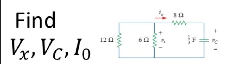
Find Vx, Vc, lo 12 Ω www 6Ω 892 13 + F "C 1


Q: * Find the current through the diode in the circuit shown. Assume the diode to be ideal. A 50 Ω w R₁…
A:
Q: A distribution substation is used to supply a factory by a single phase transmission line. The…
A: A single phase transmission line is a method of transmission of data using a single conductor. In a…
Q: 14. The operational amplifier circuit shown in the following figure includes a thermistor. V+ 100 (2…
A: Since you have asked multiple questions, we will solve the first question for you. If you want any…
Q: 1 52 V 2 452 www E V₂ ww 10 2-22 M 2A 100 4 12 V4 3 www C 2.12 ww 5n SA 3.2 ≤42 0 1A
A:
Q: Find the Thevenin's and Norton's Equivalent circuit at a. terminal a - b b. Terminal c - d -j4Ω d…
A: As per our guidelines we are supposed to answer only one question at a time. Please repost the…
Q: Problem 18. The standing-wave ratio on a mis- matched line is calculated as 1.60. If the incident…
A: Given, Standing wave ratio, s = 1.60 Incident power arriving at the transmission, Pt=200 mW…
Q: Consider the circuit shown below where the battery has an emf of = 5.9 V, the resistors have the…
A: A circuit shown below where the battery has emf of ε=5.9 V. Resistance values : R1=7.1ΩR2=R3=4Ωand…
Q: at (1000 r.p.m) to reduce the speed to half
A: Series DC motor- A type of DC motor in which armature winding is connected or fabricated in series…
Q: Q1: For the circuit shown in fig.(1), the supply current Is i(t)=10+4 sin500t+2 sin1500t Amp. Find…
A: Inductive reactance directly proportional to frequency Capacitive reactance inversely proportional…
Q: The current flowing through a heating element is 5 A when a p.d. of 35 V is applied across it. Find…
A: Given, The current flowing through a heating element, I=5 A Potential difference across this, V=35 V
Q: Problem 1 Find i, and the power developed in the dependent current source, 2xx- 6Ω 3Ω 5 Ω ww 2V |+…
A: The circuit diagram is shown below,
Q: Q2/Explan the method to compensation of bias current, offset voltage,Offset current and maximum…
A: Q2. Offset voltage will usually introduce minor faults in any op-amp circuit. Unlike the advantages…
Q: Find the total power required for the three radiators WITHOUT using PSPICE.
A: Voltage in the parallel circuit remain same across the components Current in parallel circuit can…
Q: 36V (b) Find v1 v2 v3 v4 1502 V₁ 4023 V₂ Va ww 50 792
A:
Q: 0 Question 2 For the circuit given, what is the angle by which the current lags the voltage? 1000…
A:
Q: Problem 18. The standing-wave ratio on a mis- matched line is calculated as 1.60. If the incident…
A: Given here standing wave ratio on a mismatched line is 1.60 Incident power arriving at termination…
Q: Input What is the value of the output voltage for the 311 comparator circuit shown below if the…
A: For the above given circuit diagram we need to calculate the value of output voltage of the given…
Q: Determine the causality for each of the following linear systems. a. y(n) = 0.5x(n) + 20x(n - 2) –…
A: In this question, We need to determine the causality for each of the following linear systems. a…
Q: What are the factors affecting the dielectric strength of Transformer oil?? Explain the maintenance…
A: Given Questions on transformer oil. Please find the answers below.
Q: Q० "1"- कर्म क T Q₁ "1"- T Q CLK CLK নযযযয, Q० Q1 Q1
A:
Q: The most commonly used practical binary decoders are 2-10-4 O 4-10-16 O All the of them 3-10-8 *One…
A: 1. Answer: all the of them a. It is one of the most preferred binary decoders along with the other…
Q: Given a 50 μC point charge located at the origin. find the total electric flux passing through a)…
A: Given, Point Charge Q = 50 micro coulomb at origin.
Q: A single phase transformer is given: SN 100 KVA, V₁ = 10 kV, t = 25. = 1N The short circuit…
A: Given information about a single phase transformer is written below. SN=100 kVA. V1N=10 kV. t=25.…
Q: C ~ V sine R2 Let R1 = 4 ohm, R2 = 2 ohm, reactance of the capacitor -j3 ohm and reactance of the…
A:
Q: RF carrier 10 KV at 1 MHz is amplitude modulated and index is 0.6. Peak voltage of the signal is?…
A: Given: Amplitude modulated carrier voltage, Vc=10 kV Modulation index, μ=0.6 Peak voltage of the…
Q: For the Circuit shown in fig iT = I1 Sin (1004+10") +13 (sin 300++20²) + Id sin (yoot if I +36)A In…
A: Capacitive reactance is inversely proportional to frequency Inductive reactance is directly…
Q: Q3. Determine the noise power spectrum of a RL circuit with resistance R and inductance L in series…
A: An RL circuit (sometimes called an RL filter or RL network) is an electrical circuit made up of the…
Q: Solve the problem. PROVIDE THE GIVEN, REQUIRED, EQUATION, SOLUTION, AND FINAL ANSWER WAO’s…
A: In this question we will find time period of WAO's...
Q: A 100 V peak signal at 1 GHz is applied to a transmission line of characteristic impedance 100 0,…
A: Given a transmission line has, Characteristics impedance, ZO=100 Ω Antenna impedance, ZA=75 Ω…
Q: 5. Determine the total propagation delay from each input to each output for each circuit in Fig.…
A: Given gates diagram : (a) 74FXX (b). 74HCXX
Q: Example 4.6: A varactor has a maximum capacitance of 80 pF and is used in a tuned circuit with a 100…
A:
Q: a) A 18 V voltage source is applied across a circuit consisting of a 481 ohm resistor in series with…
A: Given here a electrical circuit and asked to find voltage across resistor.
Q: In the circuit of Fig. 1, let v₁=40cos 1000t, Find the average power delivered to each resistor?…
A: The circuit diagram is shown below, Where,vs = 40 cos 1000t V
Q: 200 V/ + {25 ΚΩ 75 ΚΩ Find Vo
A: Given circuit:
Q: (a) Plot the signal x(t) and find the Fourier series coefficients {X} for x(t) using the integral…
A: Given: Consider the following signal: x1t=costut-ut-2, T0=2 To find: Plot the signal x(t) and find…
Q: Calculate the resonant frequency of the network show below. imm www R2 Az 2 46
A:
Q: (3) A digital system is required to amplify a binary encoded audio signal. The user should be able…
A:
Q: EX2: infinite line along the z-axis with 20 nc/m. Calculate the capacitance between p=10 and p=4 for…
A:
Q: Q4. Obtain the transfer function Eo(s)/E;(s). R₁ ei ww R₂ eo
A: In this question we will find transfer function of given opamp...
Q: Find the unit-impulse response for each of the following linear systems. a. y(n) = 0.5x(n) — 0.5x(n…
A:
Q: Construct the magnitude and phase plot for the following transfer functions 100(s +20) H(s) = s(s+…
A: By observing se can se that the system is single input single output. The order of the system can be…
Q: c) For the circiut shown in fig.(2), the swit find ix(t) for t>0, let R₁ R₂=1k2, R3-2k2, a. Fig.(2)
A: In this question we will find current through resistor R1 ....
Q: Balanced 3 Phase Supply A CC PC S BCN A 90 Balanced 3 Phase Load IN B The 3-phase load consumes a…
A: Methods of power measurement in three phase circuit One wattmeter method Two wattmeter method…
Q: Find the Thevenin's and Norton's equivalent circuit 30 Ω 110 Ω 120/45° V 60 2 Μ www wj5 Ω
A: Given circuit is shown below. To find the thevenin's equivalent open the capacitance
Q: EX2: infinite line along the z-axis with 20 nc/m. Calculate the capacitance between p=10 and p=4 for…
A: given here some calculations and asked to explain it.
Q: H.W z²+z X(z)= 3 (2-1) ³² (2-²)
A:
Q: Q2. Explain the implementation of conventional (deterministic) and statistical (probabilistic)…
A: Insulation Coordination was introduced to arrange the electrical insulation levels of different…
Q: Classify IC logic circuits based on the package density, i.e. the number of devices in an IC chip.
A: We will refer the classification of IC chip.
Q: Q/ derive Ri High Pass Filter? R₂
A: Given data, Circuit diagram is given as,
Q: Determine the value of Vx in Figure 4 using mesh analysis
A: It is given that:

Step by step
Solved in 3 steps with 2 images


- In this section, we will investigate the function of the PN generator in the context of the transmitter (Tx) and receiver (Rx) circuits through the lens of a simplified example.Which of the following is the expression defining the given circuit? (Z and A are LSB. U1 is 8x1 multiplexer integrated.)Using a basic example, we will examine the function of the PN generator in the context of the transmitter (Tx) and receiver (Rx) circuits.