For the amplifier circuit shown, determine the current gain Ai = lo/Ils using ideal feedback equation. 0.1mA De current source 20KO Volt 01 2KO lo(t) 1KO 1mA Ist) 0.1KO De current source hfel = hfe2 = 100, hiel =30KQ , and hie2 = 1.5KO
For the amplifier circuit shown, determine the current gain Ai = lo/Ils using ideal feedback equation. 0.1mA De current source 20KO Volt 01 2KO lo(t) 1KO 1mA Ist) 0.1KO De current source hfel = hfe2 = 100, hiel =30KQ , and hie2 = 1.5KO

Power System Analysis and Design (MindTap Course List)
6th Edition
ISBN:9781305632134
Author:J. Duncan Glover, Thomas Overbye, Mulukutla S. Sarma
Publisher:J. Duncan Glover, Thomas Overbye, Mulukutla S. Sarma
Chapter12: Power System Controls
Section: Chapter Questions
Problem 12.3P

Related questions
Question
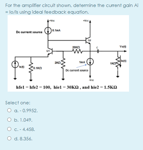
Transcribed Image Text:For the amplifier circuit shown, determine the current gain Ai
= lo/ls using ideal feedback equation.
+Vcc
0.1mA
De current source
Q2
Vo(t)
20KO
01
lo(t)
1KO
2KO
1mA
Ist)
0.1ΚΩ
Dc current source
hfel = hfe2 = 100, hiel = 30KQ , and hie2 = 1.5KQ
Select one:
O a. - 0.9952.
O b. 1.049.
O c. - 4.458.
O d. 8.356.
Expert Solution
This question has been solved!
Explore an expertly crafted, step-by-step solution for a thorough understanding of key concepts.

This is a popular solution!

Trending now
This is a popular solution!

Step by step
Solved in 2 steps

Knowledge Booster


Learn more about
Need a deep-dive on the concept behind this application? Look no further. Learn more about this topic, electrical-engineering and related others by exploring similar questions and additional content below.Recommended textbooks for you
Power System Analysis and Design (MindTap Course …
Electrical Engineering
ISBN:
9781305632134
Author:
J. Duncan Glover, Thomas Overbye, Mulukutla S. Sarma
Publisher:
Cengage Learning
Power System Analysis and Design (MindTap Course …
Electrical Engineering
ISBN:
9781305632134
Author:
J. Duncan Glover, Thomas Overbye, Mulukutla S. Sarma
Publisher:
Cengage Learning