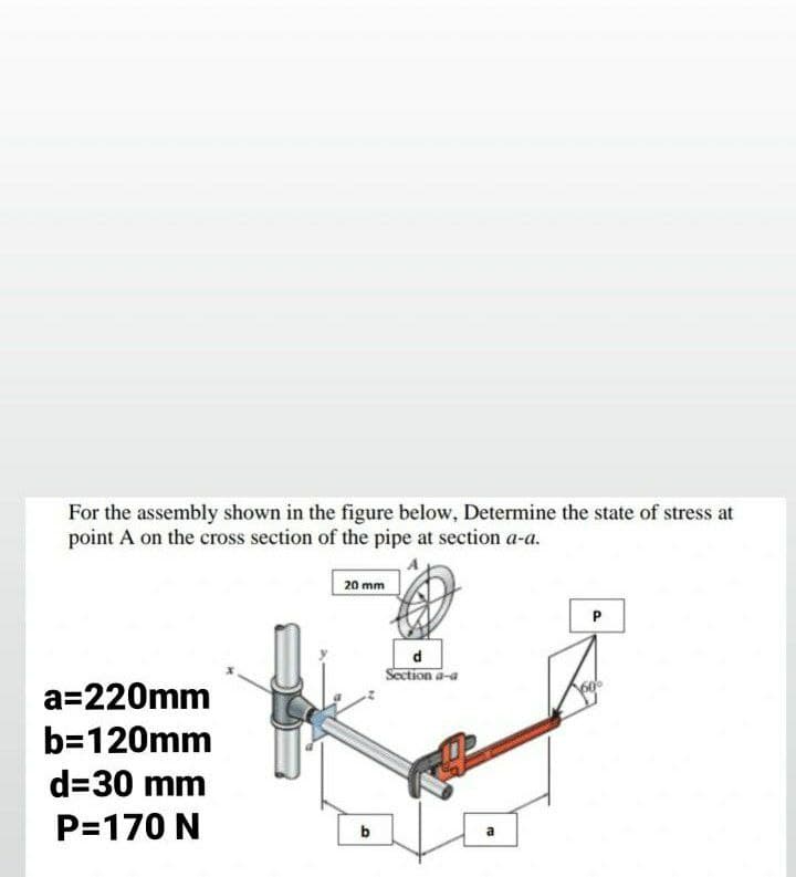
For the assembly shown in the figure below, Determine the state of stress at point A on the cross section of the pipe at section a-a. a=220mm b=120mm d=30 mm P=170 N 20 mm b d Section a-a P
For the assembly shown in the figure below, Determine the state of stress at point A on the cross section of the pipe at section a-a. a=220mm b=120mm d=30 mm P=170 N 20 mm b d Section a-a P

Mechanics of Materials (MindTap Course List)
9th Edition
ISBN:9781337093347
Author:Barry J. Goodno, James M. Gere
Publisher:Barry J. Goodno, James M. Gere
Chapter7: Analysis Of Stress And Strain
Section: Chapter Questions
Problem 7.3.7P: The normal and shear stresses acting on element A are 6500 psi, 17,300 psi, and 2900 psi (see the...

Related questions
Question
Transcribed Image Text:For the assembly shown in the figure below, Determine the state of stress at
point A on the cross section of the pipe at section a-a.
20 mm
P
d
Section a-a
a=220mm
b=120mm
d=30 mm
P=170 N
b
Expert Solution
This question has been solved!
Explore an expertly crafted, step-by-step solution for a thorough understanding of key concepts.

Step by step
Solved in 2 steps with 1 images

Knowledge Booster


Learn more about
Need a deep-dive on the concept behind this application? Look no further. Learn more about this topic, mechanical-engineering and related others by exploring similar questions and additional content below.Recommended textbooks for you
Mechanics of Materials (MindTap Course List)
Mechanical Engineering
ISBN:
9781337093347
Author:
Barry J. Goodno, James M. Gere
Publisher:
Cengage Learning
Mechanics of Materials (MindTap Course List)
Mechanical Engineering
ISBN:
9781337093347
Author:
Barry J. Goodno, James M. Gere
Publisher:
Cengage Learning