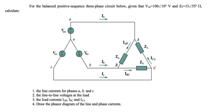
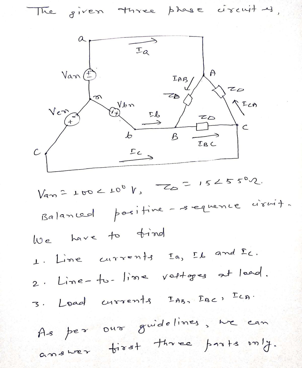
For the balanced positive-sequence three-phase circuit below, given that Van=100410° V and Za=15455° Q, calculate: ICA I, B Igc 1. the line currents for phases a, b, and e 2. the line-to-line voltages at the load 3. the load currents LAB, IBc and IcA 4. Draw the phasor diagram of the line and phase currents.
Q: Find V2 (volt) unit if E1-11V, E2--5.2V, R1=-5.2kQ, and R2-2.5k2. (Answer should roundoff to 2 decim...
A: The circuit diagram is shown below, Where,E1=11VE2=-5.2VR1=5.2kΩR2=2.5kΩ
Q: Determine V, IL, Iz and Ie for the netuork
A: First we have to check whether the voltage drop across the load resistor is greater than the zener b...
Q: If voltage v(t) = 6cos(100t – 30˚) is applied to a 50 μF capacitor, calculate the current, i(t), thr...
A:
Q: R + vo Vị 10 Vpk E 4 V
A:
Q: R-1K +2V OV IN3007 2V +1V Ground At which cycle will the waveform be cut from the diagram above? a) ...
A:
Q: Explain what RLC circuits do and how they work including transformers, where applicable.
A: It is asked to explain what RLC circuits do and how RLC circuits can work including transformers als...
Q: Q2 / Draw the root locus and find the value of K which is gain oscillatory K R(S) S(S + 1)(S + 2) C(...
A: Control systems are represented by transfer function. This can be written in both time domain and s...
Q: Three loads connected in parallel across a 1000-V (RMS), 60-Hz single-phase source. Load 1: Inductiv...
A:
Q: The resistance of tunsgten filament at 1750c° is 4ohm. Find the resistance of the filament at 20c°[t...
A: It is given that: T1=1750°C=1750+273=2023 KR1750=4 ΩT2=20°C=20+273=293 Kα=6×10⁻³ /K
Q: Q8. Explain briefly the application / use of Capacitor 1 and Capacitor 2 in the circuit shown in Fig...
A: Capacitor: This is used to store the energy in electric form.
Q: A straight conductor of 0.2 m lies on the x-axis with one end at origin. The conductor is subjected ...
A: GivenLength of straight conductor=0.2m Magnetic flux density B=0.04 ay^ TeslaVelocity v→=2.5 sin 100...
Q: Question 8 The minority carrier current in a reverse biased p-n junction diode can be increased by (...
A: Brief description: PN junction diode is a semiconductor device which is used as a switch, rectifier ...
Q: An armature has a resistance of 0.2 N at 150°C and the armature Cu loss is to be limited to 600 watt...
A: It is given that: Ra=0.2 ΩT1=150°CPcu=60 WT2=150+55=205°Cα=0.0043/°C
Q: engineering explained turbo
A: The term turbo is used for turbocharger or turbo engines in engineering. In a turbocharged engine, t...
Q: Good circuitry: Number of convenience outlets for 9-A loading on a 15-A circuit?
A: For a good circuitry - We have to determine the number of convenience outlets for 9-A loading on a 1...
Q: j30 Q all 50 2 j100 Q 60 Ω Zin 40 Q j20 C. ll
A: Given: A circuit having three resistors and two inductors Also having a capacitor To find: Zin
Q: The following system of equations was generated by applying the mesh current law to the circuit in t...
A:
Q: Find out the Laplace transform of the function x (1) =u(t – t,)
A:
Q: A3- phase, 4 – wire, 380 V supply is connected to an unbalanced load having phase impedances of ZR =...
A: Line voltage magnitude of the supply (VL) = 380 V Taking R phase voltage as reference, ...
Q: Given v1 = 20 sin (ωt + 60˚)V and v2 = 60 cos (ωt - 10˚)V, determine the phase angle between the two...
A:
Q: 6. If a varactor diode is to be connected at the red spot, where would its anode be placed? RT Vi, O...
A: As we know that the varactor diode always function in reverse biasing condition.
Q: Find the equivalent inductive reactance if the frequency is 65 Hz
A: This question belongs to circuit theory . It is about calculation of equivalent inductive reactance ...
Q: . Please have a good handwriting, some of the answers are not readable. Thank you! 2. GIVEN.(includ...
A:
Q: 7- Find Fourier transform X(jw) of; (5) 1. fel < TI x(t) 0. T < Irl <Tf2
A: 7. xt=1 , t<T10 , T1<t<T2
Q: differential Op Amp circuit is used in an experiment with R1= 75 [N] and R2=150 [2]. Deiermine the a...
A: R1 = 75 Ω R2 = 150 Ω Ei1 = 50 mV Ei2 - Ei1 = 200 mV Ei2 = 200 + Ei1 = 200 + 50 = 250 mV
Q: In a tank are 100 liters of brine containing 50 kg. total of dissolved salt. Pure water is allowed t...
A: Let Q=amount of salt in the mixture100+3-2t=100+t=Volume of mixtureAt any time tQ100+t=Conentration ...
Q: A coil resistance 5 Q and inductance of 120 mH in series with a 100 uF capacitor, is connected to a ...
A:
Q: The output of a sensor has a range ranging from 0.2 to 0.8 milli volts. Furthermore, the signal will...
A:
Q: 250 Vas=5 V 200 150 Ves=4 V 100 Ves= 3 V 50 Kac=2 V o 2 4 6 8 10 12 Drain-source voltage (V) Drain-s...
A:
Q: Question 14 The following IV characteristics is for a p-n junction diode. Five regions are labeled. ...
A: (Question 14). We need to answer from the given characteristics curve what the labelled regions bes...
Q: A 300Ω transmission line 150m long, operates at 400kHz with attenuation coefficient of 2.4 x10^(-3) ...
A: A 300Ω transmission line 150m long, operates at 400kHz with an attenuation coefficient of 2.4 x10^(-...
Q: Record the current through each resistor. Record the voltage across each resistor. Current Voltage R...
A: It is given that:
Q: Consider the circuit shown below R Qn clock X S The circuit acts as (A) output remains stable at “O"...
A:
Q: An alternating current of frequency 60HZ has a maximum value of 12A. Write down the equation for its...
A:
Q: and B. 800 A 0.0252 500 V 0.032 0.022 500 A
A:
Q: determine:IBQ,ICQ,VCEQ,VB,VC,VBC if beta is equal to 248
A:
Q: ŠOLVE THE FFG. PROBLEMS. I. USE ALL NET WORK ANALYSIS 0:52 TO SOLVE POR THE FFG. O1552 4. CURRENT IN...
A: This question belongs to electrical circuit theory . It is based on the concept of nodal analysis , ...
Q: Given the System: BUS, IO MW GI PEAK LOAD : 15 MW 24 HRS JOMW G2 A M) ENERGY : 240 MWH G3 IS A STAND...
A: Given: The system: To find: Determine the Utilization Factor of the system shown.
Q: What did you learn about the Republic Act No. 7920? "New Electrical Engineering Law." (150 words)
A: New electrical Engineering law: In this law provision of composition, power, and function of the bo...
Q: A CI is desired for the true average stray-load loss ? (watts) for a certain type of induction motor...
A:
Q: Fill in the blanks with the colors of the resistors corresponding to their values
A: The color-coding in the resistor is used to identify the value of the resistor along with the tolera...
Q: Consider the combinational circuit shown 1. Derive the Boolean expressions for T1 through T4. Evalua...
A:
Q: For the network shown in the figure below calculate the net input to the output neuron. 0.3 X, 0.2 1...
A:
Q: Find the voltage gain of the op amp circuit 20 kn 80 kn3 24 kn 1 k
A:
Q: What is the frequency swing of an FM broadcast transmitter when modulated 80%? (Ans: 60 kHz)
A:
Q: B- Determinate the output logic function (Y) & truth table for the following logic Circuit?
A: It is given that: a) b)
Q: Find the input impedance of circuit shown at w = 10 rad/s. 0.5 mF 80 2 8 H ll Zin 1 mF 200 2 Answer:...
A:
Q: IDD (2 Points) 80*10^-3A 8*10^-5 A 0.8*10^-3A 8*10^-6A
A: According to guidelines we are allowed to do only first question . Post again for remaining question...
Q: amplitude modulated by a sinusoid.
A: Note- “Since you have posted a question with multiple sub-parts, we will solve first three subparts ...
Q: Obtain the differential equation of all straight lines with algebraic sum of the intercept fixed E a...
A: The differential equation of all straight lines with algebraic sum of the intercept fixed as k.
Step by step
Solved in 4 steps with 4 images
- The three-phase source line-to-neutral voltages are given by Ean=100,Ebh=10+240, and Ecn=10240volts. Is the source balanced? (a) Yes (b) NoIn a balanced three-phase Y-connected system with a positive-sequence source, the line-to-line voltages are 3 times the line-to-neutral voltages and lend by 30. (a) True (b) FalseA balanced -connected impedance load with (12+j9) per phase is supplied by a balanced three-phase 60-Hz,208-V source, (a) Calculate the line current, the total real and reactive power absorbed by the load, the load power factor, and the apparent load power, (b) Sketch a phasor diagram showing the line currents, the line-to-line source voltages, and the -load currents. Use Vab as the reference.
- One advantage of balanced three-phase systems over separate singlephase systems is reduced capital and operating costs of transmission and distribution. (a) True (b) FalseFigure 2.33 gives the general -Y transformation. (a) Show that the general transformation reduces to that given in Figure 2.16 for a balanced three-phase load. (b) Determine the impedances of the equivalent Y for the following impedances: ZAB=j10,ZBC=j20, and ZCA=j25. ZAB=ZAZB+ZBAC+ZCZAZCZA=ZABZCAZAB+ZBC+ZCAZBC=ZAZB+ZBAC+ZCZAZAZB=ZABZBCZAB+ZBC+ZCAZCA=ZAZB+ZBAC+ZCZAZBZA=ZCAZBCZAB+ZBC+ZCALet a series RLC network be connected to a source voltage V, drawing a current I. (a) In terms of the load impedance Z=ZZ, find expressions for P and Q, from complex power considerations. (b) Express p(t) in terms of P and Q, by choosing i(t)=2Icost. (c) For the case of Z=R+jL+1/jC, interpret the result of part (b) in terms of P,QL, and Qc. In particular, if 2LC=1, when the inductive and capacitive reactances cancel, comment on what happens.
- Figure 3.32 shows the oneline diagram of a three-phase power system. By selecting a common base of 100 MVA and 22 kV on the generator side, draw an impedance diagram showing all impedances including the load impedance in per-unit. The data are given a follows: G:90MVA22kVx=0.18perunitT1:50MVA22/220kVx=0.10perunitT2:40MVA220/11kVx=0.06perunitT3:40MVA22/110kVx=0.064perunitT4:40MVA110/11kVx=0.08perunitM:66.5MVA10.45kVx=0.185perunit Lines I and 2 have series reactances of 48.4 and 65.43, respectively. At bus 4, the three-phase load absorbs 57 MVA at 10.45 kV and 0.6 power factor lagging.A single-phase source is applied to a two-terminal, passive circuit with equivalent impedance Z=3.045, measured from the terminals. The source current is i(t)=22cos(t)kA. Determine the (a) instantaneous power, (b) real power, (c) reactive power delivered by the source, and (d) source power factor.It is stated that (i) balanced three-phase circuits can be solved in per unit on a per-phase basis after converting - load impedances to equivalent Y impedances. (ii) Base values can be selected either on a per-phase basis or on a three-phase basis. (a) Both statements are true. (b) Neither is true. (c) Only one of the above is true.
- Does an open connection permit balanced three-phase operation? - (a) Yes (b) NoFor a balanced- load supplied by a balanced positive-sequence source. the line currents into the load are 3 times the -Ioad currents and lag by 30. (a) True (b) FalseA three-phase line, which has an impedance of (2+j4) per phase, feeds two balanced three-phase loads that are connected in parallel. One of the loads is Y-connected with an impedance of (30+j40) per phase, and the other is -connected with an impedance of (60j45) per phase. The line is energized at the sending end from a 60-Hz, three-phase, balanced voltage source of 1203V (rms. line-to-line). Determine (a) the current, real power. and reactive power delivered by the sending-end source: (b) the line-to-line voltage at the load: (C) the current per phase in each load: and (d) the total three-phase real and reactive powers absorbed by each load and by the line. Check that the total three- phase complex power delivered by the source equals the total three-phase power absorbed by the line and loads.