For the beam in figure 1, find the value and location of the largest tensile and compressive stresses. There may be more than one candidate location for each of these. 3.2 kN/m 2 1.9 kN.m Im A 3m 2m Figure 1 Figure 2 The cross section shown in Figure 2 is 125x75x8 UA the cross section and material properties are shown below; (Note that in the tables, the horizontal and vertical coordinate n and p, and are right and up respectively. Table 26 Unequal Angles - x-axis and y-axis - Dimensions and Properties Designation Nominal Mass Actual Radii Thickness per Thickness About x-axis About y-axis Torsion Tan Designation Constant Alpha Gross Coordinate metre Area of of Centroid Cross Leg-size Root Toe (b,-t) (b,-t) Section b, x b, t r 5, t A Рап y Z V₁ mm mm mm ka/m mm mm mm mm² mm mm 10 mm mm 10 mm mm 125 x 75 x 12 UA 17.7 12.0 10 UA 14.2 9.5 8 UA 11.8 7.8 8.0 5.0 9.42 5.25 2260 8.0 5.0 12.2 6.89 1810 8.0 5.0 15.0 8.62 1500 43.3 18.4 42.3 17.5 3.20 41.5 16.8 2.68 3.91 83.2 83.8 84.2 59.7 31.8 Z Y₁ Z S r 10-mm³ mm 10 mm 10mm³ 47.0 65.5 34.6 113 81.4 41.6 38.2 59.3 53.9 33.9 94.4 65.8 58.9 45.5 33.3 80.4 54.6 V x, Z 2日 X mm 10 mm mm 0.585 19.9 42.0 0.476 19.2 42.2 0.399 18.6 10 mm³ mm 29.3 414 24.9 41.6 21.5 Z 10-mm³ mm 10 mm² 10mm 14.1 31.9 18.4 29.7 11.4 30.7 15.5 24.1 16.2 9.55 29.9 13.3 20.1 16.3 S r J mm 10 mm 16.1 110 0.356 125 x 75 x 12 UA 56.2 0.360 31.7 0.363 10 UA 8 UA Form Factor Table 27 Unequal Angles - x-axis and y-axis - Properties for Assessing Section Capacity Designation Yield Stress About x-axis About y-axis Yield Stress Form Factor About x-axis About y-axis Designation Load A Load C Load B Load D Load A f k₁ Z Z Z Z f k Z Load C Z Load B Z Load D Z mm mm mm MPa 10mm 10 mm 10'mm³ 10 mm MPa 10 mm 10 mm 10/mm³ 10-mm³ 300PLUS AS/NZS 3679.1-350 125 x 75 x 12 UA 300 1.00 68.6 70.5 20.6 21.2 340 1,00 67.6 70.5 20.3 21.2 125 x 75 x 12 UA 10 UA 320 1.00 51.6 572 15.5 17.2 360 1.00 50.6 57.2 15.2 17.2 10 UA 8 UA 320 0.964 39.8 46.0 119 14.3 360 0.931 38.8 44.7 11.6 14.3 8 UA Table 28 Unequal Angles - n-axis and p-axis - Dimensions and Properties Designation About n-axis About p-axis Product of 2nd Moment of Area Designation P Z P. Z S Z n₂ 6 mm mm mm 10 mm mm 10°mm³ mm 10 mm 10 mm mm 10 mm mm 10°mm³ mm 10'mm³ 10 mm mm 10 mm² 125 x 75 x 12 UA 3.54 43.3 818 81.7 43.3 77.3 39.6 0.958 18.4 52.0 56.6 16.9 31.4 20.6 -105 125 x 75 x 12 UA 10 UA 2.88 42.3 68.2 827 34.9 62.5 39.9 0.789 17.5 45.2 575 13.7 25.1 20.9 -0.867 10 UA 8 UA 2.41 415 58.1 83.5 28.9 52.0 40.1 0.664 16.8 39.6 58.2 114 20.7 21.0 -0.731 8 UA Value (MPa) Does this stress exceed the yield stress of the member? Location on beam (draw sketch) Location on Cross section (draw sketch) Largest tensile stress Largest compressive stress
For the beam in figure 1, find the value and location of the largest tensile and compressive stresses. There may be more than one candidate location for each of these. 3.2 kN/m 2 1.9 kN.m Im A 3m 2m Figure 1 Figure 2 The cross section shown in Figure 2 is 125x75x8 UA the cross section and material properties are shown below; (Note that in the tables, the horizontal and vertical coordinate n and p, and are right and up respectively. Table 26 Unequal Angles - x-axis and y-axis - Dimensions and Properties Designation Nominal Mass Actual Radii Thickness per Thickness About x-axis About y-axis Torsion Tan Designation Constant Alpha Gross Coordinate metre Area of of Centroid Cross Leg-size Root Toe (b,-t) (b,-t) Section b, x b, t r 5, t A Рап y Z V₁ mm mm mm ka/m mm mm mm mm² mm mm 10 mm mm 10 mm mm 125 x 75 x 12 UA 17.7 12.0 10 UA 14.2 9.5 8 UA 11.8 7.8 8.0 5.0 9.42 5.25 2260 8.0 5.0 12.2 6.89 1810 8.0 5.0 15.0 8.62 1500 43.3 18.4 42.3 17.5 3.20 41.5 16.8 2.68 3.91 83.2 83.8 84.2 59.7 31.8 Z Y₁ Z S r 10-mm³ mm 10 mm 10mm³ 47.0 65.5 34.6 113 81.4 41.6 38.2 59.3 53.9 33.9 94.4 65.8 58.9 45.5 33.3 80.4 54.6 V x, Z 2日 X mm 10 mm mm 0.585 19.9 42.0 0.476 19.2 42.2 0.399 18.6 10 mm³ mm 29.3 414 24.9 41.6 21.5 Z 10-mm³ mm 10 mm² 10mm 14.1 31.9 18.4 29.7 11.4 30.7 15.5 24.1 16.2 9.55 29.9 13.3 20.1 16.3 S r J mm 10 mm 16.1 110 0.356 125 x 75 x 12 UA 56.2 0.360 31.7 0.363 10 UA 8 UA Form Factor Table 27 Unequal Angles - x-axis and y-axis - Properties for Assessing Section Capacity Designation Yield Stress About x-axis About y-axis Yield Stress Form Factor About x-axis About y-axis Designation Load A Load C Load B Load D Load A f k₁ Z Z Z Z f k Z Load C Z Load B Z Load D Z mm mm mm MPa 10mm 10 mm 10'mm³ 10 mm MPa 10 mm 10 mm 10/mm³ 10-mm³ 300PLUS AS/NZS 3679.1-350 125 x 75 x 12 UA 300 1.00 68.6 70.5 20.6 21.2 340 1,00 67.6 70.5 20.3 21.2 125 x 75 x 12 UA 10 UA 320 1.00 51.6 572 15.5 17.2 360 1.00 50.6 57.2 15.2 17.2 10 UA 8 UA 320 0.964 39.8 46.0 119 14.3 360 0.931 38.8 44.7 11.6 14.3 8 UA Table 28 Unequal Angles - n-axis and p-axis - Dimensions and Properties Designation About n-axis About p-axis Product of 2nd Moment of Area Designation P Z P. Z S Z n₂ 6 mm mm mm 10 mm mm 10°mm³ mm 10 mm 10 mm mm 10 mm mm 10°mm³ mm 10'mm³ 10 mm mm 10 mm² 125 x 75 x 12 UA 3.54 43.3 818 81.7 43.3 77.3 39.6 0.958 18.4 52.0 56.6 16.9 31.4 20.6 -105 125 x 75 x 12 UA 10 UA 2.88 42.3 68.2 827 34.9 62.5 39.9 0.789 17.5 45.2 575 13.7 25.1 20.9 -0.867 10 UA 8 UA 2.41 415 58.1 83.5 28.9 52.0 40.1 0.664 16.8 39.6 58.2 114 20.7 21.0 -0.731 8 UA Value (MPa) Does this stress exceed the yield stress of the member? Location on beam (draw sketch) Location on Cross section (draw sketch) Largest tensile stress Largest compressive stress

Mechanics of Materials (MindTap Course List)
9th Edition
ISBN:9781337093347
Author:Barry J. Goodno, James M. Gere
Publisher:Barry J. Goodno, James M. Gere
Chapter7: Analysis Of Stress And Strain
Section: Chapter Questions
Problem 7.2.19P: At a point on the surface of an elliptical exercise machine, the material is in biaxial stress with...

Related questions
Question
Please answer the attached question which includes all the necessary background information sourced together for your convenience
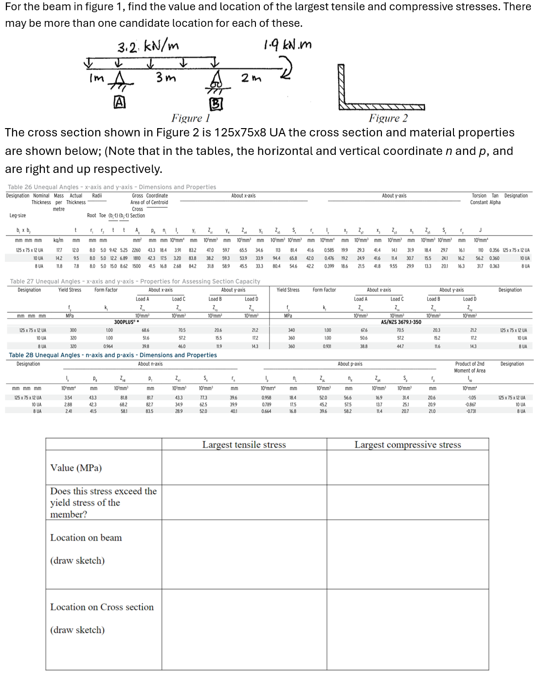
Transcribed Image Text:For the beam in figure 1, find the value and location of the largest tensile and compressive stresses. There
may be more than one candidate location for each of these.
3.2 kN/m
2
1.9 kN.m
Im A
3m
2m
Figure 1
Figure 2
The cross section shown in Figure 2 is 125x75x8 UA the cross section and material properties
are shown below; (Note that in the tables, the horizontal and vertical coordinate n and p, and
are right and up respectively.
Table 26 Unequal Angles - x-axis and y-axis - Dimensions and Properties
Designation Nominal Mass Actual Radii
Thickness per Thickness
About x-axis
About y-axis
Torsion Tan Designation
Constant Alpha
Gross Coordinate
metre
Area of of Centroid
Cross
Leg-size
Root Toe (b,-t) (b,-t) Section
b, x b,
t
r 5,
t
A
Рап
y
Z
V₁
mm mm mm
ka/m
mm
mm mm
mm²
mm mm 10 mm
mm
10 mm
mm
125 x 75 x 12 UA
17.7
12.0
10 UA
14.2
9.5
8 UA
11.8
7.8
8.0 5.0 9.42 5.25 2260
8.0 5.0 12.2 6.89 1810
8.0 5.0 15.0 8.62 1500
43.3 18.4
42.3 17.5 3.20
41.5 16.8 2.68
3.91
83.2
83.8
84.2
59.7
31.8
Z Y₁ Z S r
10-mm³ mm 10 mm 10mm³
47.0
65.5 34.6 113 81.4 41.6
38.2 59.3 53.9 33.9 94.4 65.8
58.9 45.5 33.3 80.4 54.6
V
x,
Z
2日 X
mm 10 mm mm
0.585 19.9
42.0 0.476 19.2
42.2 0.399 18.6
10 mm³
mm
29.3 414
24.9
41.6
21.5
Z
10-mm³ mm 10 mm² 10mm
14.1 31.9 18.4 29.7
11.4 30.7 15.5 24.1 16.2
9.55 29.9 13.3 20.1 16.3
S
r
J
mm
10 mm
16.1
110 0.356 125 x 75 x 12 UA
56.2 0.360
31.7 0.363
10 UA
8 UA
Form Factor
Table 27 Unequal Angles - x-axis and y-axis - Properties for Assessing Section Capacity
Designation Yield Stress
About x-axis
About y-axis
Yield Stress
Form Factor
About x-axis
About y-axis
Designation
Load A
Load C
Load B
Load D
Load A
f
k₁
Z
Z
Z
Z
f
k
Z
Load C
Z
Load B
Z
Load D
Z
mm mm mm
MPa
10mm
10 mm
10'mm³
10 mm
MPa
10 mm
10 mm
10/mm³
10-mm³
300PLUS
AS/NZS 3679.1-350
125 x 75 x 12 UA
300
1.00
68.6
70.5
20.6
21.2
340
1,00
67.6
70.5
20.3
21.2
125 x 75 x 12 UA
10 UA
320
1.00
51.6
572
15.5
17.2
360
1.00
50.6
57.2
15.2
17.2
10 UA
8 UA
320
0.964
39.8
46.0
119
14.3
360
0.931
38.8
44.7
11.6
14.3
8 UA
Table 28 Unequal Angles - n-axis and p-axis - Dimensions and Properties
Designation
About n-axis
About p-axis
Product of 2nd
Moment of Area
Designation
P
Z
P.
Z
S
Z
n₂
6
mm mm mm
10 mm
mm
10°mm³
mm
10 mm
10 mm
mm
10 mm
mm
10°mm³
mm
10'mm³
10 mm
mm
10 mm²
125 x 75 x 12 UA
3.54
43.3
818
81.7
43.3
77.3
39.6
0.958
18.4
52.0
56.6
16.9
31.4
20.6
-105
125 x 75 x 12 UA
10 UA
2.88
42.3
68.2
827
34.9
62.5
39.9
0.789
17.5
45.2
575
13.7
25.1
20.9
-0.867
10 UA
8 UA
2.41
415
58.1
83.5
28.9
52.0
40.1
0.664
16.8
39.6
58.2
114
20.7
21.0
-0.731
8 UA
Value (MPa)
Does this stress exceed the
yield stress of the
member?
Location on beam
(draw sketch)
Location on Cross section
(draw sketch)
Largest tensile stress
Largest compressive stress
AI-Generated Solution

Unlock instant AI solutions
Tap the button
to generate a solution
Recommended textbooks for you
Mechanics of Materials (MindTap Course List)
Mechanical Engineering
ISBN:
9781337093347
Author:
Barry J. Goodno, James M. Gere
Publisher:
Cengage Learning
Mechanics of Materials (MindTap Course List)
Mechanical Engineering
ISBN:
9781337093347
Author:
Barry J. Goodno, James M. Gere
Publisher:
Cengage Learning