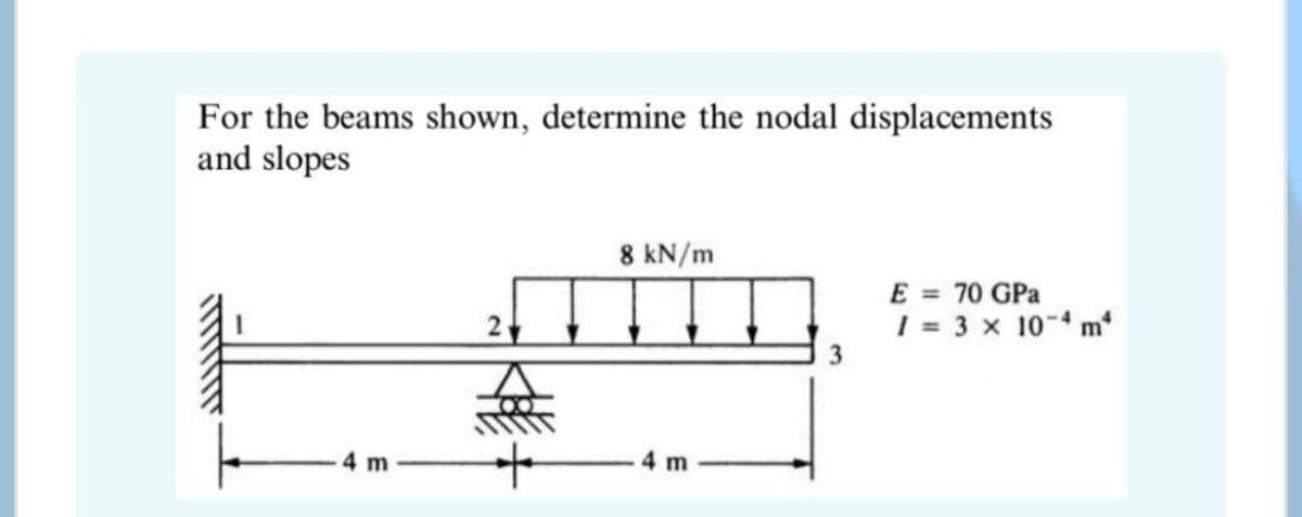
For the beams shown, determine the nodal displacements and slopes 8 kN/m E = 70 GPa 1 = 3 x 10- m 2 to 4m 4 m


Q: For the given parallel forces, determine its resultant and its location from point A. 25KN/m 20KN/m…
A:
Q: For the beam shown in figure, determine the nodal displacements/slopes. 5 kN/m E = 210 GPa I= 2x10⁴m…
A: Given : E = 210 GPA I = 2 × 10^- m4 Solution :
Q: Analyze the given structure using Virtual Work Method Determine the displacement at point B
A:
Q: 61 V = 51 N- 48 K 1,5 m 1.5 m 3 m 5 m 180 mm 21 221 = h, 18 тт h2. bị %3D 21
A:
Q: Q. 2 Determine the vertical displacement of Joint A shown in Q2 if members AB and BC experience a…
A: Trusses are structures that are widely used to carry a wide variety of loading conditions under…
Q: Sample Problem 2 Determine the components of the forces acting on each member of the frame shown.…
A:
Q: From the figure shown, find the horizontal displacement at B in kNm/EI. El is constant. 2 m 20 kN B…
A: Step 1
Q: Use the graphical method to construct the shear-force diagram and identify the magnitude of the…
A: We have to calculate magnitude of largest shear force of diagram by using graphical method
Q: For the given beam shown, determine the deflection at midspan and it's free ends. El is constant and…
A: To find deflection at midspan and at ends
Q: DETERMINE THE VALUE OF "P" SUCH THAT RAY IS TWICE AS MUCH THE VALUE OF RBY. DEFINE THE VALUES OF…
A:
Q: Q5) Compute the value of P such that AHo not more than 20 mm for the structure shown in the figure.…
A: Given that horizontal deflection at D should not exceed 20 mm EI is constant We have to find the…
Q: 2a. and 2b Solve for the resultant of the two y F = 25 kN vectors (2a). Also, determine the…
A: Consider the following figure. The coordinates of points are given below.
Q: HW1: Use the Conjugate beam method to determine the slope at A and displacement at C. El is…
A:
Q: 1. From the figure, determine a. Rx b. Ry c. Magnitude of Resultant d. The inclination of the…
A:
Q: For the given beam shown, determine the deflection at midspan and it's free ends. El is constant and…
A:
Q: Q) Analyse the structure shown in Figure using slope deflection method, support C settles by (1cm…
A:
Q: Determine the value of Eld at midspan of the simply supported beam by double integration method.…
A:
Q: Determine the reaction of supports from the beam shown in the figure using forced method. El is…
A:
Q: Q3. Find the vertical deflection of joint (b), if the modulus of elasticity (E = 30*10 kN/cm), area…
A: Given At joint e 10KN and at joint d 5KN Vertical deflection at b are to be found. By using P…
Q: Determine the joint displacements, member axial forces, and support reactions for the Baltimore…
A: Support Reactions : Due to symmetry in truss system as well as loading,R1 = R9 = 120×72 = 420 kN
Q: For the shown frame: 1. Calculate support reactions. Draw B.M.D., S.F.D. and N.F.D. 2. 3. Use the…
A:
Q: For the beam shown in figure, determine the Ely at 2m from left support. 3m from right support and…
A:
Q: 4.) THE MAGNITUDES OF THE THREE FORCES ACTING ON THE PLATE ARE T1=100 KN, T2 80 KN AND T3 = 50 KN.…
A: To find Resultant force
Q: 3. Determine the slope and vertical displacement of point A on the beam shown in the accompanying…
A:
Q: For the truss in the figure, compute (a) the vertical displacement of joint C, (b) the horizontal…
A:
Q: Problem I. Analyze the beam using flexibility matrix method. Take El = constant. ş kN/m 50 kN 5m 3m…
A: Given EI is constant We have to analyze the beam by Flexibility method and calculate the support…
Q: 2/24 At what angle 8 must the 400-lb force be applied in order that the resultant R of the two…
A:
Q: Use Virtual Work Method to answer the questions below considering the truss shown in the figure.…
A:
Q: Given figure shown. The magnitude of the Resultant Force is 48.5898 kN. The angle 0 is 40 degrees…
A:
Q: Horizontal component FH is Blank 1 KN Vertical component Fv is Blank 2 KN Distance of FH from point…
A:
Q: Problem I. Analyze the beam using flexibility matrix method. Take El = constant. 5 kN/m 50 kN 5m 3 m…
A: The beam is shown in the figure EI is constant We have to analyze the beam by flexibility method and…
Q: Sm 20N
A: Varginons theorem : It states that resultant moment of a non concurrent force system is equal to the…
Q: the magnitude of the horizontal displacement
A: Given, A truss EFGH is shown in the fugure.Axial rigidity =R P is the magnitude of external…
Q: The beam shown in Fig. 10.6(a) is to be analyzed to determine the member end forces and deflections…
A: A beam is an essential element in the construction of any building or structure. It resists loading…
Q: The horizontal and vertical components of a force F acting on point O are respectively, Fx = +700 lb…
A: We knowFR=Fx2+Fy2
Q: By slope-deflection equations, determine the maximum positive bending moment in portion CD.…
A:
Q: Q2: Use the Vector Polygon Method to calculate the resultant and its direction of the four coplanar…
A: Resultant force 9.5 kN and acts at 59.16° with horizontal. Answer is calculated as follows :
Q: 1. Location of resultant force from x -axis. 12.7 m b) 6 c) 5 m a) m 2. Location of resultant force…
A: the resultant force on x-y plane islet ,R=resultant forcethen,R=20+40-30R=30 KNdownwardfrom the…
Q: 100 kN - m 150 kN 25 kN/m A B 4 m 4 m 4 m 2 m' 2 m
A:
Q: Refer to the figure shown a = 23 x 10/°c E = 70 GPa 900 mm2 11.7 x 10/°C %3D E = 200 GPa 1,200 mm2 A…
A: Useful given data For member- AB Length (LAB) = 300 mm Cross section area (A1) = 1200 mm2 E1 =…
Q: Determine the nodal displacements at C and E. El=100,000 KN.m². Express answers in mm or radians. 20…
A:
Q: Determine the vertical displacement of joint E of the truss. Each member has a cross-sectional area…
A:
Q: 3 in B. 10in 0.5in-
A: Given Data:Shear force= 20000lbh= 10inb=3int=0.5in
Q: B The cross-sectional area of members AB, BC and CD equals 500 mm?. The cross-sectional area of all…
A:
Q: H.W.2 Determine the horizontal and vertical components of the water forces exerted on the segmental…
A:
Q: Determine the y-component of the resultant of the concurrent forces in KN below. F1 = 337 KN, 01 =…
A:
Q: 3. The simply supported beam in the figure has a rectangular cross section 120 mm wide and 200 mm…
A: Draw the shear force and bending moment diagram of the given beam:
Q: Determine the magnitude of the horizontal displacement of point C (in mm). Each member has a…
A:
Q: Q. 2 Determine the vertical displacement of Joint A shown in Q. 2, if members AB and BC experience a…
A:


Trending now
This is a popular solution!

Step by step
Solved in 2 steps with 2 images


- A 140 KN force with a slope of 4 vertical and 7 horizontal islocated on the second quadrant. Determine its y- component.a. 121.55 KNb. 69.46 KNc. 112.55 KNd. 96.46 KNFor the beam and loading shown below, determine the beam deflection at point H. Assume that EI = 5.6 × 10⁴ kN·m2 is constant for the beam; P = 40 kN, LAB = 3.9 m, LBH = 3.9 m.3.) For the given couple-force system shown, determine the horizontal component of Q. P= 335 KN Q= 44 KN R=74 KN-m Z=263 KN
- Referring to Prob. 259, what value of T acting at x=3 ft from B will keep the bar horizontalUSING DOUBLE INTEGRATION METHOD Consider 250 mm x 250 mm (bxh) mm section and e = 100000 MPa DETERMINE VERTICAL REACTION AT B DETERMINE SLOPE REACTION AT B DETERMINE DEFLECTION AT D Values: A = 9.4 M B = 5.5 M C = 10.6 KN/M D = 33 KNA simply supported beam carries a concentrated load of 31 kN at 7 meters from the left support (1 meters from the right support). Use EI = 80,000 kN-m2. Solve for the slope at the left support in degrees.
- Given the figure below. Use UNIT LOAD METHOD in determining the maximum deflection at midspan. E and I are constant. 1. What is the reaction at A of the real beam? 2. In constructing the virtual beam and determining the maximum deflection, where must be the 1-unit load be placed? 3. What is the reaction at the support of the virtual beam? 4. In solving the maximum deflection at midspan, how many portions or segments must the beam be divided so that the real and virtual loadings are continuous in each segment? 5. Consider segment AB of the real beam, with x measured from A, what is the moment equation M_(AB ) ? 6. In question 4, what are the limiting values of x? 7. Consider segment AB of the virtual beam, with x measured from A, what is the moment equation? 8. Analyzing segment BC of the real beam, with x measured from A, what is the moment equation M_BC? 9. In the given beam, if the 50 KN load is moved 2m closer to A and deflection at midspan is desired, how many segments must the…Refer to Figure P6.4. A strip load of q = 900 lb/ft2 is applied over a width B = 36 ft. Determine the increase in vertical stress at point A located z = 15 ft below the surface. Given: x = 27 ft. Figure P6.4Consider a 175-mm-long segment of a simply supported beam. The internal bending moments on the left and right sides of the segment are 75 kN-m and 80 kN-m, respectively. The cross-sectional dimensions of the flanged shape are shown in the accompanying figure. Assume b1 = 120 mm, b2 = 50 mm, b3 = 210 mm, d1 = 75 mm, d2 = 175 mm, d3 = 75 mm. Determine the maximum horizontal shear stress in this segment of the beam.
- The T-shaped beam shown above is supporting a concentrated load P at its free end. The beam has an allowable bending stress of ?????? = 250 MPa and an allowable shear stress of ?????? = 100 MPa. a) Determine the distance to the neutral axis (?̅), second moment of area (?), and the section modulus (?) of the cross-section.b) Draw the shear force diagram (SFD) and bending moment diagram (BMD) of the beam. On your diagrams, express the values of shear and moment in terms of the applied load P.c) Determine the maximum value of P such that bending failure will not occur.d) Determine the maximum value of P such that shear failure will not occur.e) Based on your answers to (c) and (d), what is the maximum load P that can be applied to the beam? Is this beam bending or shear governed?For the beam shown, EI = constant, E = 200 GPa and I = 6x10⁶mm⁴. Determine the following: A. Slope at B B. Deflection at C C. Location of the maximum deflection D. Maximum deflectionThe left half of the simply supported beam carries a uniformly distributed load of internsity 600N/m. A.Compute the value of ??? at midspan. B.If E= 10GPa, determine the smallest value of I that limits the midspan displacement to 1/360th of the span.