
Principles of Foundation Engineering (MindTap Course List)
8th Edition
ISBN: 9781305081550
Author: Braja M. Das
Publisher: Cengage Learning
expand_more
expand_more
format_list_bulleted
Concept explainers
Videos
Textbook Question
Chapter 6, Problem 6.4P
Refer to Figure P6.4. A strip load of q = 900 lb/ft2 is applied over a width B = 36 ft. Determine the increase in vertical stress at point A located z = 15 ft below the surface. Given: x = 27 ft.
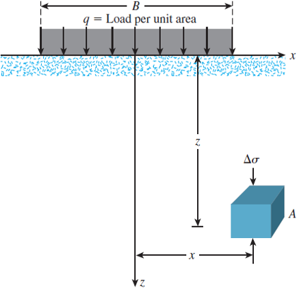
Figure P6.4
Expert Solution & Answer
Want to see the full answer?
Check out a sample textbook solution
Students have asked these similar questions
Refer to Figure P6.3. Determine the vertical stress increase Δσ at point A with the values q1 = 90 kN/m, q2 = 325 kN/m, x1 = 4 m, x2 = 2.5 m, and z = 3 m.
Referring to Figure Q2 (a), the vertical stress increase at point A is 25 kN/m2due to application of line loads q1 and q2. Determine the magnitude of q2.
Refer to Figure P6.4. A strip load of q = 900 lb/ft2 is applied over a width B = 36 ft. Determine the increase in vertical stress at point A located z = 15 ft below the surface. Given: x = 27 ft.
Chapter 6 Solutions
Principles of Foundation Engineering (MindTap Course List)
Ch. 6 - A flexible circular area is subjected to a...Ch. 6 - Point loads of magnitude 100, 200, and 400 kN act...Ch. 6 - Refer to Figure P6.3. Determine the vertical...Ch. 6 - Refer to Figure P6.4. A strip load of q = 900...Ch. 6 - Refer to Figure 6.6, which shows a flexible...Ch. 6 - Repeat Problem 6.5 with B1 = 4 ft, B2 = 10 ft, L1...Ch. 6 - Use Eq. (6.14) to determine the stress increase ()...Ch. 6 - Prob. 6.8PCh. 6 - Prob. 6.9PCh. 6 - Prob. 6.10P
Knowledge Booster


Learn more about
Need a deep-dive on the concept behind this application? Look no further. Learn more about this topic, civil-engineering and related others by exploring similar questions and additional content below.Similar questions
- The soil profile at a site is shown Figure P16.3. Find the total horizontal normal stresses at A and B, assuming at-rest conditions.arrow_forwardRepeat Problem 10.12 for q = 700 kN/m2, B = 8 m, and z = 4 m. In this case, point A is located below the centerline under the strip load. 10.12 Refer to Figure 10.43. A strip load of q = 1450 lb/ft2 is applied over a width with B = 48 ft. Determine the increase in vertical stress at point A located z = 21 ft below the surface. Given x = 28.8 ft. Figure 10.43arrow_forwardPoint loads of magnitude 9, 18, and 27 kN act at A, B, and C, respectively(Figure 6.27). Determine the increase in vertical stress at a depth of 3 mbelow point D. Using Westergaard solution. Use μs = 0.4.arrow_forward
- Point loads of magnitude 100, 200, and 400 kN act at B, C, and D, respectively (Figure P6.2). Determine the increase in vertical stress at a depth of 6 m below point A. Use Boussinesq’s equation.arrow_forwardA strip load of q =53 kN/m^3 is applied over a width B =11m. Determine the increase in vertical stress in kPa at point A located z = 4.6 m below the surface. x = 8.2marrow_forwardReferring in the Fig. 2 below, B = 6m and q =150 kPa. For Point P, z = 2m and x = 1.5m. Determine the vertical stress at Point P.arrow_forward
- Using Boussinesq’s Equation determine the vertical stress increase ΔϬz, at point C at a depth 3.0 meters , if the point loads at A,B and D are 200 KN, 400KN and 600KN respectively. ΔϬzC =_____________KN/m2.arrow_forwardDue to the application of line loads q1 and q2, the vertical stress increase, ∆?? , at point A is 42 kN/m2 . Determinearrow_forwardDetermine the shear stress at points A, B, C andD for the following section. Also determine the maximum shear stress, then plot the shear stress distribution. Given: V = 10 kN.arrow_forward
- A circular area having a radius of 3 m carries a uniformly distributed of 90 kPa is applied to the ground. Compute the total vertical stress in kN/m^2 increment due to this uniform load if the unit weight of soil is 18.40 kN/m^3 at point 6 m below the center of the circular area. a. 27.26 b. 137.66 c. 129.02 d. 135.17arrow_forwardFind the expressions to calculate the maximum normal and shear stresses for a circular profile: d (diameter)= 0.30 marrow_forwardA 5-m-diameter tank supported on the surface of a soil deposit imposes a bearing pressure of 225 kPa (225 kN/m2). For a point 4 m below the tank base, compare the vertical stress increase due to the tank loading when:(a) the Westergaard conditions are assumed.(b) the 60° approximation is assumed.arrow_forward
arrow_back_ios
SEE MORE QUESTIONS
arrow_forward_ios
Recommended textbooks for you
 Principles of Foundation Engineering (MindTap Cou...Civil EngineeringISBN:9781305081550Author:Braja M. DasPublisher:Cengage Learning
 Principles of Geotechnical Engineering (MindTap C...Civil EngineeringISBN:9781305970939Author:Braja M. Das, Khaled SobhanPublisher:Cengage Learning
 Principles of Foundation Engineering (MindTap Cou...Civil EngineeringISBN:9781337705028Author:Braja M. Das, Nagaratnam SivakuganPublisher:Cengage Learning
Principles of Foundation Engineering (MindTap Cou...
Civil Engineering
ISBN:9781305081550
Author:Braja M. Das
Publisher:Cengage Learning
Principles of Geotechnical Engineering (MindTap C...
Civil Engineering
ISBN:9781305970939
Author:Braja M. Das, Khaled Sobhan
Publisher:Cengage Learning
Principles of Foundation Engineering (MindTap Cou...
Civil Engineering
ISBN:9781337705028
Author:Braja M. Das, Nagaratnam Sivakugan
Publisher:Cengage Learning
Stress Distribution in Soils GATE 2019 Civil | Boussinesq, Westergaard Theory; Author: Gradeup- GATE, ESE, PSUs Exam Preparation;https://www.youtube.com/watch?v=6e7yIx2VxI0;License: Standard YouTube License, CC-BY