For the capacitor circuit shown in Figure Q3(a), calculate: (i) (ii) (iii) The equivalent capacitance for the circuit, C. The total charge of the circuit and charge for each capacitor, Q. The potential difference across each capacitor, V. 3 uf 4 uf 2 uf 6 uf 12 v Figure Q3(a)
For the capacitor circuit shown in Figure Q3(a), calculate: (i) (ii) (iii) The equivalent capacitance for the circuit, C. The total charge of the circuit and charge for each capacitor, Q. The potential difference across each capacitor, V. 3 uf 4 uf 2 uf 6 uf 12 v Figure Q3(a)

Delmar's Standard Textbook Of Electricity
7th Edition
ISBN:9781337900348
Author:Stephen L. Herman
Publisher:Stephen L. Herman
Chapter20: Capacitance In Ac Circuits
Section: Chapter Questions
Problem 5PP: Three capacitors having capacitance values of 20F,40F, and 50F are connected in parallel to a 60 -...

Related questions

Question
100%
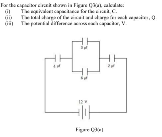
Transcribed Image Text:For the capacitor circuit shown in Figure Q3(a), calculate:
(i)
The equivalent capacitance for the circuit, C.
(ii)
The total charge of the circuit and charge for each capacitor, Q.
(iii) The potential difference across each capacitor, V.
3 uf
4 uf
2 uf
6 uf
12 V
Figure Q3(a)
Expert Solution
This question has been solved!
Explore an expertly crafted, step-by-step solution for a thorough understanding of key concepts.

Step by step
Solved in 2 steps with 2 images

Knowledge Booster


Learn more about
Need a deep-dive on the concept behind this application? Look no further. Learn more about this topic, electrical-engineering and related others by exploring similar questions and additional content below.Recommended textbooks for you
Delmar's Standard Textbook Of Electricity
Electrical Engineering
ISBN:
9781337900348
Author:
Stephen L. Herman
Publisher:
Cengage Learning
Delmar's Standard Textbook Of Electricity
Electrical Engineering
ISBN:
9781337900348
Author:
Stephen L. Herman
Publisher:
Cengage Learning