For the circuit in Problem 5, calculate the final current flowing through the inductor if the initial current through it, ir(0) = 0Amps for DC steady state. Put your values in Amps in the box below without units. Also, round off the decimal to three decimal places if needed. For the circuit in Problem 5, calculate the equivalent Thevenin voltage, Voc, in Volts as for the following circuit. Put your values in N in box below. Round off the decimals to three places if needed. Rth www C Voc
For the circuit in Problem 5, calculate the final current flowing through the inductor if the initial current through it, ir(0) = 0Amps for DC steady state. Put your values in Amps in the box below without units. Also, round off the decimal to three decimal places if needed. For the circuit in Problem 5, calculate the equivalent Thevenin voltage, Voc, in Volts as for the following circuit. Put your values in N in box below. Round off the decimals to three places if needed. Rth www C Voc

Introductory Circuit Analysis (13th Edition)
13th Edition
ISBN:9780133923605
Author:Robert L. Boylestad
Publisher:Robert L. Boylestad
Chapter1: Introduction
Section: Chapter Questions
Problem 1P: Visit your local library (at school or home) and describe the extent to which it provides literature...

Related questions
Question
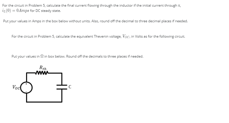
Transcribed Image Text:For the circuit in Problem 5, calculate the final current flowing through the inductor if the initial current through it,
ir(0) = 0Amps for DC steady state.
Put your values in Amps in the box below without units. Also, round off the decimal to three decimal places if needed.
For the circuit in Problem 5, calculate the equivalent Thevenin voltage, Voc, in Volts as for the following circuit.
Put your values in N in box below. Round off the decimals to three places if needed.
Rth
www
C
Voc
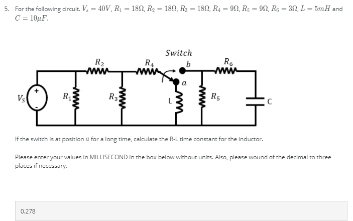
Transcribed Image Text:5. For the following circuit. V, = 40V, R1 = 180, R2 = 182, R3 = 182, R4 = 9N, R5 = 9N, R$ = 3N, L = 5mH and
C = 10µF.
%3D
%3D
Switch
R4
www
R6
R2
www
Vs
R3
Rs
If the switch is at position a for a long time, calculate the R-L time constant for the inductor.
Please enter your values in MILLISECOND in the box below without units. Also, please wound of the decimal to three
places if necessary.
0.278
www
www
www
Expert Solution
This question has been solved!
Explore an expertly crafted, step-by-step solution for a thorough understanding of key concepts.

This is a popular solution!

Trending now
This is a popular solution!

Step by step
Solved in 3 steps with 3 images

Recommended textbooks for you
Introductory Circuit Analysis (13th Edition)
Electrical Engineering
ISBN:
9780133923605
Author:
Robert L. Boylestad
Publisher:
PEARSON

Delmar's Standard Textbook Of Electricity
Electrical Engineering
ISBN:
9781337900348
Author:
Stephen L. Herman
Publisher:
Cengage Learning

Programmable Logic Controllers
Electrical Engineering
ISBN:
9780073373843
Author:
Frank D. Petruzella
Publisher:
McGraw-Hill Education
Introductory Circuit Analysis (13th Edition)
Electrical Engineering
ISBN:
9780133923605
Author:
Robert L. Boylestad
Publisher:
PEARSON
Delmar's Standard Textbook Of Electricity
Electrical Engineering
ISBN:
9781337900348
Author:
Stephen L. Herman
Publisher:
Cengage Learning
Programmable Logic Controllers
Electrical Engineering
ISBN:
9780073373843
Author:
Frank D. Petruzella
Publisher:
McGraw-Hill Education

Fundamentals of Electric Circuits
Electrical Engineering
ISBN:
9780078028229
Author:
Charles K Alexander, Matthew Sadiku
Publisher:
McGraw-Hill Education

Electric Circuits. (11th Edition)
Electrical Engineering
ISBN:
9780134746968
Author:
James W. Nilsson, Susan Riedel
Publisher:
PEARSON

Engineering Electromagnetics
Electrical Engineering
ISBN:
9780078028151
Author:
Hayt, William H. (william Hart), Jr, BUCK, John A.
Publisher:
Mcgraw-hill Education,