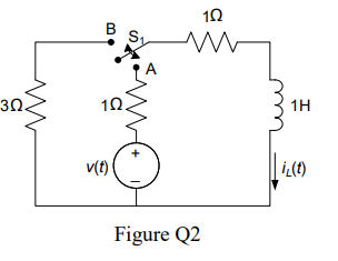
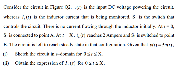
Consider the circuit in Figure Q2. v(t) is the input DC voltage powering the circuit, whereas i, (t) is the inductor current that is being monitored. Si is the switch that controls the circuit. There is no current flowing through the inductor initially. At t = 0, Sį is connected to point A. At t = X, i, (t) reaches 2 Ampere and Sj is switched to point B. The circuit is left to reach steady state in that configuration. Given that v(t) = 5u(t), (i) Sketch the circuit in s-domain for 0
Consider the circuit in Figure Q2. v(t) is the input DC voltage powering the circuit, whereas i, (t) is the inductor current that is being monitored. Si is the switch that controls the circuit. There is no current flowing through the inductor initially. At t = 0, Sį is connected to point A. At t = X, i, (t) reaches 2 Ampere and Sj is switched to point B. The circuit is left to reach steady state in that configuration. Given that v(t) = 5u(t), (i) Sketch the circuit in s-domain for 0

Introductory Circuit Analysis (13th Edition)
13th Edition
ISBN:9780133923605
Author:Robert L. Boylestad
Publisher:Robert L. Boylestad
Chapter1: Introduction
Section: Chapter Questions
Problem 1P: Visit your local library (at school or home) and describe the extent to which it provides literature...

Related questions
Question
Transcribed Image Text:10
B
30.
1H
v(t)
Figure Q2
Transcribed Image Text:Consider the circuit in Figure Q2. v(t) is the input DC voltage powering the circuit,
whereas i, (t) is the inductor current that is being monitored. S1 is the switch that
controls the circuit. There is no current flowing through the inductor initially. At t = 0,
S, is connected to point A. At t = X, i, (1) reaches 2 Ampere and S, is switched to point
B. The circuit is left to reach steady state in that configuration. Given that v(t) = 5u(t),
(i)
Sketch the circuit in s-domain for 0<t<X.
(ii)
Obtain the expression of I, (s) for 0<t<X.
Expert Solution
This question has been solved!
Explore an expertly crafted, step-by-step solution for a thorough understanding of key concepts.

Step by step
Solved in 2 steps with 2 images

Knowledge Booster


Learn more about
Need a deep-dive on the concept behind this application? Look no further. Learn more about this topic, electrical-engineering and related others by exploring similar questions and additional content below.Recommended textbooks for you
Introductory Circuit Analysis (13th Edition)
Electrical Engineering
ISBN:
9780133923605
Author:
Robert L. Boylestad
Publisher:
PEARSON

Delmar's Standard Textbook Of Electricity
Electrical Engineering
ISBN:
9781337900348
Author:
Stephen L. Herman
Publisher:
Cengage Learning

Programmable Logic Controllers
Electrical Engineering
ISBN:
9780073373843
Author:
Frank D. Petruzella
Publisher:
McGraw-Hill Education
Introductory Circuit Analysis (13th Edition)
Electrical Engineering
ISBN:
9780133923605
Author:
Robert L. Boylestad
Publisher:
PEARSON
Delmar's Standard Textbook Of Electricity
Electrical Engineering
ISBN:
9781337900348
Author:
Stephen L. Herman
Publisher:
Cengage Learning
Programmable Logic Controllers
Electrical Engineering
ISBN:
9780073373843
Author:
Frank D. Petruzella
Publisher:
McGraw-Hill Education

Fundamentals of Electric Circuits
Electrical Engineering
ISBN:
9780078028229
Author:
Charles K Alexander, Matthew Sadiku
Publisher:
McGraw-Hill Education

Electric Circuits. (11th Edition)
Electrical Engineering
ISBN:
9780134746968
Author:
James W. Nilsson, Susan Riedel
Publisher:
PEARSON

Engineering Electromagnetics
Electrical Engineering
ISBN:
9780078028151
Author:
Hayt, William H. (william Hart), Jr, BUCK, John A.
Publisher:
Mcgraw-hill Education,