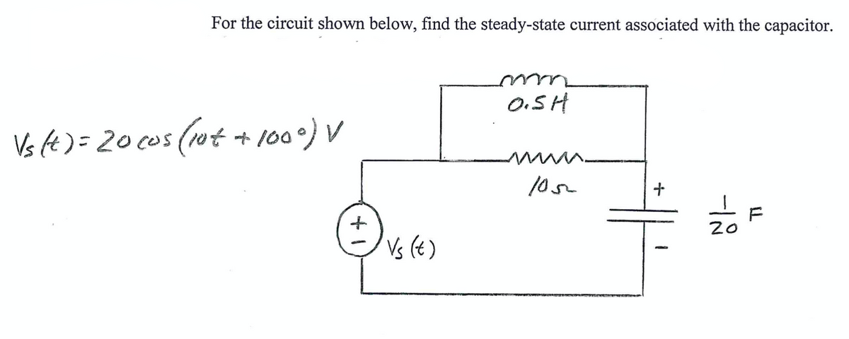
For the circuit shown below, find the steady-state current associated with the capacitor. 0.SH Vs fe )= 20 cos (1ut + 100°) V F 20 Vs (t)


Q: A given RLC circuit (Resistor-Inductor-Capacitor) has the following components: R = 4.4 Ohms L =…
A: The reactance offered by capacitor in RLC circuit (XC) is given by: Where, The capacitance of…
Q: A given RLC circuit (Resistor-Inductor-Capacitor) has the following components: R = 4.1 Ohms L =…
A: The reactance offered by inductor in RLC circuit (XL) is given by: Where, The inductance of…
Q: A series RLC circuit having a resistance of 8 ohm, inductance of 50 mH and capacitance of 90 µF is…
A: We have been give an RLC circuit with, Resistance (R) = 8 Ω Inductor (L) = 50 mH = 50 * 10-3 H…
Q: Example 14.8. A 15-mH inductor is in series with a parallel combination of an 80 2 resistor and 20…
A: Given, Inductance, L = 15 mH Resistance, R=80 Ω Capacitance, C = 20 μF Angular frequency, ω=1000…
Q: Q1. Using Thevenin's theorem, perform the conversion showed in the image below. Perform transient…
A:
Q: For the circuit shown ,if the switch on at t=0, determine Vr, ir and vz as a function of time Ro
A: This circuit has a switch and is opened for a long time. It will close at time t=0. a) t=0, (t<0)…
Q: Determine the equivalent capacitance between points a and b. 8 µF 6 µF a 6 µF 3 µF: 12 μF bo 10 µF
A: When two capacitor connected in series Ceq=( C1*C2)/(C1+C2) When capacitor connected in parallel…
Q: Determine i(t) for t > 0. Capacitor V = 0 at t<0
A: The displacement current through a capacitor is given as Here, VC is the voltage across the…
Q: Consider the circuit given below. t=0 0223 Su(-1) µA 4 mF 1 mH Calculate the maximum inductor…
A:
Q: A series RLC circuit is constructed employing component values R = 100 Sa and L = 1.5 mH along with…
A: In this we will find Capacitance C with help of data...And find impedance and current for series…
Q: The capacitor of external defibrillator must be loaded at 1500V, in order to generate a two-phase…
A: CAPACITOR: Any two conducting surfaces separated by an insulating material is called a capacitor od…
Q: t(ms) 8 12 shown above, is applied to a 5 µF capacitor. „The power of the capacitor at t=8 will be:
A:
Q: . Find the energy stored in each capacitor in the circuit shown under de conditions. 102 202 MA 2012…
A:
Q: In the series circuit of Fig, the source has voltage amplitude 20.0 V and angular frequency 5.40 x…
A: Since you have posted a question with multiple sub-parts, we will solve first three sub-parts for…
Q: Quest aired on television. It is moved to position b, finally, at time t= 0. t = 0 a 5 k2 20 kΩ 2 µF…
A: In this question, Energy in the capacitor E= 1/2 CV2 J. Capacitor never change instant voltage.…
Q: 1. An RLC circuit consists of three elements: a resistor (R), and inductor (L) and a capacitor (C),…
A: Given the circuit, as shown below: Given the initial values: i(0)=0 A and q(0)=1.5 C Given: R=200…
Q: A system with the following pole-zero plot is marginally stable. 3m(s) (2) 5. Refs) -2 -1 True False
A: Any control system is said to be marginally stable if there exist poles at the jw axis without any…
Q: The voltage across the terminals of the 5µF capacitor is 30 cos (4000t + 25°) V. Calculate (a) the…
A: Since you have posted a question with multiple sub-parts, we will solve the first three sub-parts…
Q: Problem 5.3 Find the total inductance of the circuit shown. 33 mH 2.4 mH Lq=5.6 mH L,=4 mH ell
A:
Q: Consider the given circuit with vi=3V, R1=20K, Rf=50K, R2=10K, R3=20K, C=2μF. Assuming that the…
A: In this question we will find output voltage of opamp...
Q: For the circuit shown ,if the switch on at t=0 , determine Vr, ir and vz as a function of time Ro
A:
Q: An RIC series circuit has R = 2 ohms. L= 20 mH, and a variable capacitance Cas shown below. The…
A:
Q: usé differential equation method to: 1. Find the initial capacitor voltage V (t0) when switch moves…
A: We need to find out voltage across capacitor in given circuit
Q: A 0.1 henry inductor, a 4x10^(-3) farad capacitor, a O ohm resistor, and a voltage source having a…
A:
Q: 20 502 m SMF 2H ↓ + ilt) A) Find the Second order differental equation respective to the Capacitor…
A:
Q: 1. In the given circuit, determine the current i(t) if va 12 V and vs(t) = 74.93sin(1000t)V.…
A: In this question, We need to Find the inductor current at time t= 0+ and t=0- expression of the…
Q: The input to the circuit shown below is the voltage of the voltage source Vs(t) = 5 cos (2t + 45°) V…
A:
Q: 2. Please find the time constant and capacitance value (C) of a simple RC circuit by using its…
A:
Q: The voltage across a 2µF capacitor is given by the waveform shown below. Determine and sketch the…
A: Given voltage waveform across capacitor of 2 (micro F) is =
Q: From the circuit, find the voltage drop across the capacitor. Let v.(1) = 4 u(t) V and at time t=0…
A: The solution is given below
Q: A 1.5 H coil has R of 70 2. The coil is energised by e= 149 sin 314 t. obtain the expression for the…
A:
Q: 2) An LC circuit is made by attaching a 0.2221 H inductor is connected across a variable capacitor…
A:
Q: Example 3.1: Find the steady-state response of the system 1 H(z) = (z – 0.1)(z – 0.5) - | due to the…
A: Given System function and sampled sinusoid input . We need to determine the steady state response.…
Q: 2. Please find the time constant and capacitance value (C) of a simple RC circuit by using its…
A: In an electric circuit, the transients are due to energy storing elements. If the network contains…
Q: The voltage across the terminals of the 5μF capacitor is 30 cos (4000t + 25°) V. Calculate (a) the…
A: Given, Capacitor=C=5μF=5×10⁻⁶F Voltage across Capacitor Terminal=V(t)=30cos4000t+25°V
Q: R a 十 Vs VC The RC circuit shown is subject to an input step voltage of magnitude 1.0 volts. If…
A: The voltage across the capacitor in RC circuit is given by: Where, The voltage supplied by the…
Q: The voltage v(t) = 12 cos(60t+45°) is applied to a 0.1 H inductor. Find the steady state current…
A: In this question we need to find a steady state current through the inductor.
Q: The circuit shown is at steady state before the switch closes at time t = 0. Determine the inductor…
A: Given circuit is =
Q: A coil of inductance 710.61 µH and resistance 20 Q is connected in parallel with a variable…
A: In this practical tank circuit is given....We have to find out capacitance value, dynamic impedance…
Q: The voltage 8 sin (400t) is applied to a series RLC circuit, with R = 200 Q, L = 0.1 H, and C = 1 µF…
A:
Q: Example 2.22 Find the steady-state response of the system 1 H(2) = (z – 0.1)(z - .5) due to the…
A: The solution is given below
Q: Q.9: For the circuit shown, if (it=5+3sin@t+1.5sin2@t) Amp. Write the: J22 1. Non-sinusoidal current…
A: 1. Current equation in capacitance is by current division rule- ic =j26-j8×iT…
Q: For the shown LC circuit, the switch closed at t=0. If C = 323 µF, L = 20 mH, and E = 200 V, then…
A: Given that E=200VL=20 mHC=323 μFt=5 ms Draw the s-doamin circuit of given circuit diagram Apply…
Q: The voltage across a 100-μF capacitor takes thefollowing values. Calculate the expression for…
A: Given capacitor voltage and value of capacitor is – Value of current is –
Q: For the circuit bellow, 12 V 30 2 1 F What is the initial voltage of the capacitor at t> 0? What is…
A:
Q: Given a circuit with a Time domain values: v(t) = 10 cos(1000t) R = 100 N L = 10 mH C = 10 µF %3D…
A:
Q: Given That: Is=0.0058, R1=7000 N, R2=6000 N, L=26 H, C=2 F, The circuit shown below under dc…
A:
Q: Decide the stability of the system, whose characteristic equation is given by S5 +254 +5S³ + 10s² +…
A:

Step by step
Solved in 2 steps


- A resistor of 100 Ω, a coil of 4.50 μH, and a capacitor of 220 pF are in parallel. What is the admittance vector at 6.50 MHz? Provide illustration of the circuit.A series RLC circuit is constructed using component values R = 100 £2 and L = 1.5 mH along with a sinusoidal voltage source vs. If Qo= 7, determine (a) the magnitude of the impedance at 500 Mrad/s; (b) the current which flows in response to a voltage vs = 2.5 cos(425 × 10%t) V.The voltage across the terminals of the 5μF capacitor is 30 cos (4000t + 25°) V. Calculate (a) the capacitive reactance; (b) the impedance of the capacitor; (c) the phasor current I; and (d) the steady-state expression for i (t). 5 μF + v i
- In the circuit shown , the dc current source is replaced with a sinusoidal source that delivers a current of 1.2cost A. The circuit components are R=1 Ω, C=625 mF, and L=1.6 H. Find the numerical expression for V(s).A circuit is constructed with an AC generator, a resistor, capacitor and inductor as shown. The generator voltage varies in time as ε =Va - Vb = εmsinωt, where εm = 120 V and ω = 726 radians/second. The values for the remaining circuit components are: R = 62 Ω, L = 95.6 mH, and C = 13.8μF. 4) What is t1, the first time after t = 0 when the voltage across the inductor is zero? 6) What is VC = Vd - Va, the voltage across the capacitor, at time t = 0? Note that VC is a signed number.For the network shown below, the switch is closed on to position 1 when t = 0 and then moved to position 2 when t = 20 ms. Determine the voltage across the capacitor when t = 30 ms. Also plot the response of this circuit from time, t = 0 to t = 40 ms.
- 12. 7.12 In the circuit , let Ig represent the dc current source, σrepresent the fraction of initial energy stored in the inductor that isdissipated in to seconds, and L represent the inductance. 1. a) Show thatR=Lln[1/(1−σ)]2to4.b 1- Draw the SFG diagram 2- When8u(t)is applied as input, enter the steady-state value of the system into the solution field given belowWrite an expression for the output voltage for the circuit as shown if υ1 = 0.5 sin 2000πt, and υ2 is generated by the circuit as shown with υ3 = 0.5 sin 10,000πt? Assume VCC = −VEE = 10 V, IEE = 500 μA, R1 = R3 = 2 kΩ, and R = 10 kΩ.
- The circuit is operating inthe sinusoidal steady state. The capacitor is adjusted until the current igis in phase with the sinusoidal voltage vg.1. Specify the capacitance in microfarads if vg=80 cos5000t V.2. Give the steady-state expression for ig when C has the value foundin (a).Differential equations Calculate the capacitor load on an LRC circuit in series when L = 1/4h, R=20Ω, C=1/300f, E(t)=0V, q(0)= 4C, i(0)=0AIs the load on the capacitor ever zero? Pls dont skip stepsAssume that the circuit in the image has been connected for a very long time. (a) As time approaches infinity, what wtll happen to the capacitor and inductor? (b) From your answer in (a), draw the equivalent circuit (label appropriately).(c) From your circuit in (b), determine the "steady-state" or "final" values of Vc, lc, IL and VL