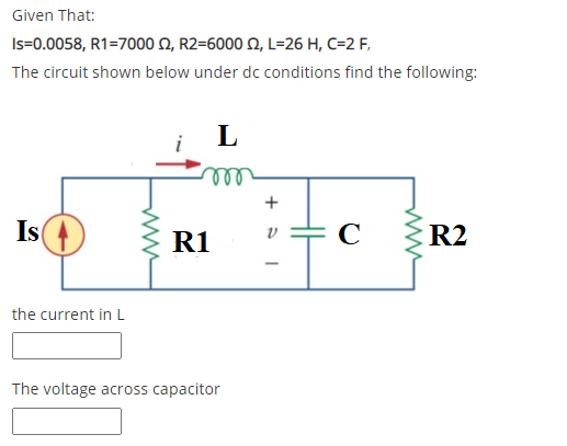
Given That: Is=0.0058, R1=7000 N, R2=6000 N, L=26 H, C=2 F, The circuit shown below under dc conditions find the following: L Is R1 C R2 the current in L The voltage across capacitor H +


Q: Write your ID No. Let C = 80 µF and L = 2mH if the last digit of your ID No. is from 0-4; otherwise,…
A:
Q: Calculate the current in an RLC circuit with resistances R=11 ohms, L=0.1 H, and C=10^-2 F that is…
A:
Q: 2. Please find the time constant and capacitance value (C) of a simple RC circuit by using its…
A: The capacitor stores the charge in the form of voltage. The current can be exponential decaying or…
Q: Questions 39 Given: C, L The circuit below is under steady DC conditions. 6 N C F 8 H lll 1020° A L…
A:
Q: 2) Please find the time constant and capacitance value (C) of a simple RC circuit by using its…
A: Given graph of simple RC circuit is - Given values are - R=840kohm
Q: + C1 Vc 1F 2 ohm R3 V1 10V 1 ohm L1 1 ohm 1H
A:
Q: wwww Vc For the given circuit above, the circuit values are as follows; L=700 mH, C = 450 µF and R =…
A: Calculate the initial current in the circuit. EL0=12LiL0210×10-3=12700×10-3iL02iL02=0.02857iL0=0.17…
Q: Determine the current through a 100-p F capacitor if its voltage as a function of time is given by…
A:
Q: t=0 s 10 - (1)3A 3102 1o2 ve(t)=0.1F 10Ω 102 v(t) 0.1F O A) 5 J O B) O J C) 0.2 J O D) 0.8 J O E)…
A: In an electric circuit, the transients are due to energy storing elements. If the network contains…
Q: L Data: C = 10 μF; L = 400 mH; R₁ = R₂ = 200 R₂ M + 200 V C At t = 0, the switch is closed. The…
A:
Q: 1. Transient analysis t=0 R2=20 R1=30 V1=45 V (+ R3=60 L=7 mH V2=26 V (+ 0 the switch is The switch…
A:
Q: Ri Re The circuit is at steady state. R1 = 2 ko, R2 = 3 kQ , L = 30 H, C = 15 µF, and V1=50 Volts…
A: The circuit as mentioned is in a steady state hence we can conclude that 1. The inductor acts as a…
Q: I In the circuit below, find the value of the voltage across the capacitor assuming that the value…
A: We need to determine the current through the inductor.
Q: 1. An RLC circuit consists of three elements: a resistor (R), and inductor (L) and a capacitor (C),…
A: Given the circuit, as shown below: Given the initial values: i(0)=0 A and q(0)=1.5 C Given: R=200…
Q: For the circuit shown in figure 1, assume that the switch was closed for a long time before t = 0.…
A: Note: We are authorized to answer three subparts at a time, since you have not mentioned which part…
Q: B-For the circuit shown, the switch S is closed at t-0, and the voltage readings for capacitor (Vc)…
A: From given details we will find out the capacitor and E and time constant value .
Q: Q2) Obtain mathematical model and block diagram for the RLC system shown. R c= co RLC circuit Where:…
A: In order to give a mathematical model for the series RLC circuit, Differential equations need to be…
Q: 2.The current in the 50mH inductor in figure is known to be 100mA for t<0. The inductor voltage for…
A:
Q: P.3. R₂ M 200 V C At t = 0, the switch is closed. The initial energy stored in the inductor and the…
A:
Q: B-For the circuit shown, the switch S is closed at t-0, and the voltage readings for capacitor (Vc)…
A:
Q: 22. A 25-µF capacitor is connected to an emf given by v(t) = (160V)sin(120rt). (a) What is the…
A: Given Capacitance C=25 μF EMF vt=160sin120πt Angular frequency ω=120π (a) The capacitive reactance…
Q: Write the general form of, and determine the exact response of the capacitor voltage for the…
A: A electrical device which stores electrical energy in an electric field, known as a Capacitor.…
Q: Solve the circuit by obtaining the state equation. The initial condition voltage value of the…
A: The given diagram can be modified as
Q: Given That: Is=0.0083, R1=9000N, R2=4000 N, L=36 H, C=6 F, The circuit shown below under dc…
A:
Q: 2. The expression for capacitor voltage in an RC circuit (assuming no initial charge) when DC…
A: Note: Since you have not specified any question to be answered, as per our honor code, we are…
Q: For L1=13, L2=18, L3=15, L4=33, L5=78, L6=32, L7=15, L8=59, L9=34 in the circuit shown below, Find…
A: In the circuit Inductance are connected in series parallel combination. Find the equivalent…
Q: The initial voltages on capacitors C1 and C2 in the circuit shown in have been established by…
A: After closing the switch circuit can be shown as
Q: 8. Find the energies stored in all capacitors and inductors in the circuit shown assuming…
A: We know behaviour of inductor and capacitor at steady state , then we will find current and voltage…
Q: let C = 100 uF and L = 10mH. a. Calculate the value of R that will make the initial energy stored in…
A:
Q: 6 - In the circuit given below let R=2 Q,&=10 V, and C=1µF. The capacitor is uncharged before…
A: For the given transient circuit we need to find a current in the circuit at 2 microseconds
Q: Assume that at the instant the 2 A currentsource is applied to the circuit the initial current in…
A: Let V be the voltage across all the elements in the circuit. Redraw the circuit for t > 0 in the…
Q: 4) b) The circuit of figure given below shows a capacitor, two ideal batteries, two resistors, and a…
A: It is given that: C=10 μFε1=1 Vε2=2.2 VR1=0.2 ΩR2=0.4 Ω
Q: Find the voltage across the capacitor vc for: a) t=2 s b) t = 4 s c) t= 6 s d) t= 8 s Sketch vc to…
A: Capacitor voltage equation is Vc=Vc(∞) +(Vc(initial)-Vc(∞))e-tΓVc(∞)…
Q: 2. Please find the time constant and capacitance value (C) of a simple RC circuit by using its…
A: Capacitor is an electrical component used to store electrical energy in the form of charge. It…
Q: Consider the circuit shown in the figure. (Assume that C, = 3 µF, C, = 5 UF. C, = 6 UF, and C = 4…
A:
Q: 4. The switch shown in Figure has been open for a long time before closing at t = 0. Write the…
A:
Q: The voltage across the terminals of a 250 nF capaci- tor is S50 V, (Aje-4000r + A2te 4000) V, t2 0.…
A: Given, V0=50 V i0=400 mA C=250 nF where V0 is the initial value of voltage across capacitor, i0 is…
Q: Given the circuit below, solve for the following: R1 4ohm R2 1ohm 5u(-t) A v. 0.5F 2H а. Derive the…
A: Apply KCL at node and write the capacitor voltage in terms of inductor current and than obtain…
Q: Consider the following circuit, with R = 20. R Assume first that v, = 12V-u(-t) and X is a capacitor…
A: Given : In the above given question they have mentioned an electrical circuit having independent…
Q: 2.39: The switch in the circuit shown in figure beside has been closed for a long time, then 12AA…
A:
Q: The voltage across a 100-μF capacitor takes thefollowing values. Calculate the expression for…
A: Given capacitor voltage and value of capacitor is – Value of current is –
Q: Q4/ For the circuit shown, the switch S is at position 2 for a long time, then it change to position…
A:
Q: T13 Class Problem 2 A 40V battery is connected to the capacitor circuit as shown. a) Find the…
A: The solution is given below
Q: 3. The circuit is at steady state before the switch opens at time t = 0. The current v(t) is given…
A:
Q: 4. The circuit is at steady state before the switch transitions from closed to open at time t = 0.…
A:
Q: Q.1 For the given circuit the Switch Sı is closed at t=0, the capacitor has and initial voltage Vo.…
A:
Q: ig (t) = 4 cos 5000 mA constant current source !! V(t) Vc(t) ic(t) Voltage across constant current…
A:
Q: Is=0.007, R1=6000 Q, R2=7000 2, L=31 H, C=1 F, The circuit shown below under dc conditions find the…
A: In the circuit, Under DC load condition, Find the current in the inductor and voltage across the…
Q: a 36: The switch in the circuit shown in figure beside has been in position "a" for a long time, and…
A: In d.c. analysis, under steady state condition a capacitor will behave as OPEN CIRCUIT. The voltage…
circuits

Step by step
Solved in 2 steps with 2 images


- IN THE CIRCUIT SHOWN, CONSIDER THAT V1=20 VDC, R1=1000 Ω, R2=3000 Ω, R3=3500 Ω AND C=1 mF.DETERMINE:A) THE TIME IT TAKES FOR THE CAPACITOR TO REACH ITS FINAL VALUE (5T), WHEN SWITCH 2 (INT 2) IS IN POSITION A AND SWITCH 1 (INT 1) IS CLOSED AT t=0,B) THE ENERGY STORED BY THE CAPACITOR ONCE IT HAS BEEN FULLY CHARGED WITH THE SAME POSITION OF SWITCHES AS ITEM A)C) ONCE THE CAPACITOR HAS BEEN FULLY CHARGED WITH SWITCH 1 CLOSED, SWITCH 2 MOVES POSITION (GOES TO B) AT A NEW t=0. NOW DETERMINE THE VALUE OF THE VOLTAGE ON THE CAPACITOR AT t=3.5 SECONDSDerive an expression for the electrical energy stored in a capacitor of capacitance C when charged to a potential difference V. If C = 2µF and V= 4V, calculate(l.) the final energy stored in the capacitor,(II.) the work done by the battery in the charging process Account for any difference between your answers in parts (I) and (II) aboveCan you please help with this question? The triangular voltage pulse shown below is applied to a 200 mF capacitor. a) Write the expressions thatdescribe vc(t) in the five time intervals t < 0, 0 ≤ t ≤ 2 , 2 ≤ t ≤ 6, 6 ≤ t ≤ 8, and t > 8. b) Derive theexpressions for the capacitor current, power, and energy for the time intervals in part (a).
- In the circuit of the figure, the switch S has been in position a for a long time; when the current through the inductor is maximum, the switch changes to position b (this instant is taken as t = 0). If the current source is iS(t) = 2.1213 cos (100πt + π/ 4). Determine: i) the value of R2 so that at t = 4 mS the current iL (t = 4mS) = 1 A. ii) The expression for the inductor current iL(t) t> 0 iii) the value of iL(t) at t = 0. iv) the expression of the inductor voltage vL(t) t> 0. v) the value of vL(0).The switch in the circuit below has been in position a for a long time. At time t = 0 the switch is thrown to position b. You are given the data: Vb = 24 V, C = 10 μF. Vc is the voltage across the capacitor. If the charge on the capacitor at time t =0.3 msec after the switch is thrown is 53.6 μC, what is the value of the resistor R? a) 40 Ω b) 0 Ω c) 20 Ω d) Not enough information.Capacitance= 4uF , Hence time constant is 5.33μs For the capacity value, calculate the estimated time to come to the final state.Plot capacitor current and voltage graphs and show if it works in harmony with the time constant you calculated. NOTE: if you want you can use falstad online circuit simulator.
- Given the circuit below with the switch closed for a long time, then opening at t=0, and with the values R1=193KΩ, R2=186KΩ, R3=107KΩ, calculate the capacitor voltage at t =0.Design a single circuit element containing one inductor, one capacitor and one resistor with v(t) of = vt=4+2e-3tV and it=-3e-3tA for t>0 . Also specify the value of the inductance, capacitance and the resistance of the tree elementThe triangular voltage pulse shown below is applied to a 200 mF capacitor. a) Write the expressions thatdescribe vc(t) in the five time intervals t < 0, 0 ≤ t ≤ 2 , 2 ≤ t ≤ 6, 6 ≤ t ≤ 8, and t > 8. b) Derive theexpressions for the capacitor current, power, and energy for the time intervals in part (a).
- Given the circuit below with the switch closed for a long time, then opening at t=0, and with the values R1=129KΩ, R2=128KΩ, R3=103KΩ, calculate the time constant, τ, for the capacitor voltage solution for at t >0.An electrical circuit contains a resistance R ohms and a capacitor C farads which initially holds acharge Q coulombs. The rate of discharge of the capacitor is given by the equation dQ/dt + Q/RC =0where t is the time in seconds. If R = 80,000 ohms and C = 0·3x 10^-6 farads and also Q = 0·0015coulombs initially, find the equation connecting Q and t. Find Q when t = 0·02 seconds and also twhen Q = 0·001 coulombs(a) Specify v1(0) and v2(0) for determining the equivalent circuit involving the capacitors for t≥0. : (b) At t0=0.2 s, determine the currennt i(t0=0.2 s): (c) At t0=0.2 s, determine υ1(t0) and υ2(t0):