For the circuit shown below, Given that V 100Z0°Vm and I = 30245°Ams then the values of P, and Q3 are %3D given as Is VAR 600 Capacitive 1200 W 1400 VAR 800 W Vs Inductive ○ Pッ %3D0.6kw Q3 = 2.3 kVAr capacitive P, = 0.6 kW Q3 = 0.7 kVAr inductive P = 0.12 kW Q = 2.92 kVAr capacitive
For the circuit shown below, Given that V 100Z0°Vm and I = 30245°Ams then the values of P, and Q3 are %3D given as Is VAR 600 Capacitive 1200 W 1400 VAR 800 W Vs Inductive ○ Pッ %3D0.6kw Q3 = 2.3 kVAr capacitive P, = 0.6 kW Q3 = 0.7 kVAr inductive P = 0.12 kW Q = 2.92 kVAr capacitive

Power System Analysis and Design (MindTap Course List)
6th Edition
ISBN:9781305632134
Author:J. Duncan Glover, Thomas Overbye, Mulukutla S. Sarma
Publisher:J. Duncan Glover, Thomas Overbye, Mulukutla S. Sarma
Chapter2: Fundamentals
Section: Chapter Questions
Problem 2.17MCQ: Consider the load convention that is used for the RLC elements shown in Figure 2.2 of the text. A....

Related questions
Question
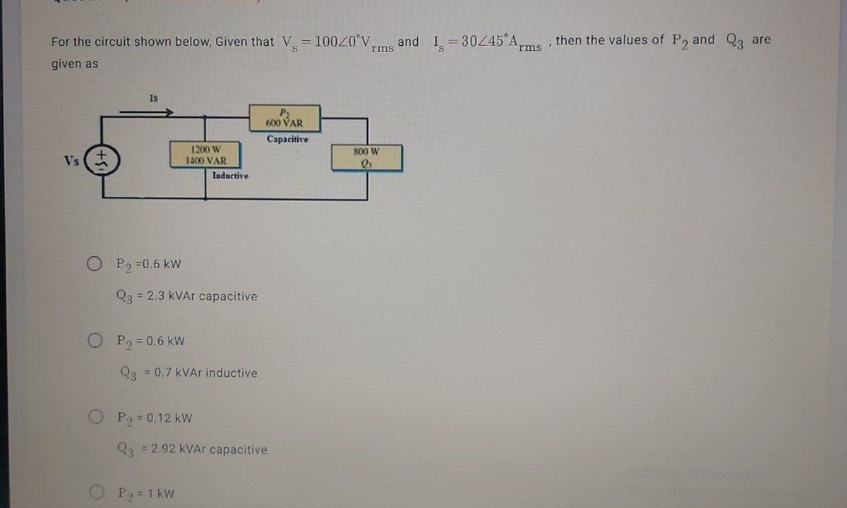
Transcribed Image Text:For the circuit shown below, Given that V 10020°V,
I = 30245 Arms'
then the values of P, and Q3 are
and
rms
given as
Is
600 VAR
Capacitive
1200 W
800 W
Vs
1400 VAR
Inductive
P, =0.6 kW
Q3 = 2.3 kVAr capacitive
P, = 0.6 kW
Qa = 0.7 kVAr inductive
P2 = 0.12 kW
Q2 = 2.92 kVAr capacitive
Activate Wincow
P, = 1 kW
Expert Solution
This question has been solved!
Explore an expertly crafted, step-by-step solution for a thorough understanding of key concepts.

Step by step
Solved in 5 steps with 1 images

Knowledge Booster


Learn more about
Need a deep-dive on the concept behind this application? Look no further. Learn more about this topic, electrical-engineering and related others by exploring similar questions and additional content below.Recommended textbooks for you
Power System Analysis and Design (MindTap Course …
Electrical Engineering
ISBN:
9781305632134
Author:
J. Duncan Glover, Thomas Overbye, Mulukutla S. Sarma
Publisher:
Cengage Learning
Power System Analysis and Design (MindTap Course …
Electrical Engineering
ISBN:
9781305632134
Author:
J. Duncan Glover, Thomas Overbye, Mulukutla S. Sarma
Publisher:
Cengage Learning