Unless given, use the: POLAR FORM for voltage and current, RECTANGULAR FORM for impedance. (30pts) Consider the following circuit, supplied by a 500mARMS current source with a 30° phase shift (i.e. Isource=500230⁰ mA). R1 100 ww L1 320 mH C1 16 μF a. What is the total impedance of the circuit? b. What is the voltage drop on the 100-ohm resistor, R1? c. Is the circuit inductive, capacitive, or neither (resistive)? d. Draw the phasor diagram of the voltage and current at R1. e. What is the total power (apparent) delivered by the current source? f. Draw the phasor diagram of the voltage and current at the source. 11 sine 50 Hz ell
Unless given, use the: POLAR FORM for voltage and current, RECTANGULAR FORM for impedance. (30pts) Consider the following circuit, supplied by a 500mARMS current source with a 30° phase shift (i.e. Isource=500230⁰ mA). R1 100 ww L1 320 mH C1 16 μF a. What is the total impedance of the circuit? b. What is the voltage drop on the 100-ohm resistor, R1? c. Is the circuit inductive, capacitive, or neither (resistive)? d. Draw the phasor diagram of the voltage and current at R1. e. What is the total power (apparent) delivered by the current source? f. Draw the phasor diagram of the voltage and current at the source. 11 sine 50 Hz ell

Introductory Circuit Analysis (13th Edition)
13th Edition
ISBN:9780133923605
Author:Robert L. Boylestad
Publisher:Robert L. Boylestad
Chapter1: Introduction
Section: Chapter Questions
Problem 1P: Visit your local library (at school or home) and describe the extent to which it provides literature...

Related questions

Concept explainers
Sinusoids And Phasors
Sinusoids are defined as the mathematical waveforms that are used to describe the nature of periodic oscillations.
Circuit Theory
Electric circuits are a network that comprises of a closed-loop, which helps in providing a return path for the current through a switch. When the switch is activated, the load operates, and the current accepts a path to finish the circuit at a low potential level from the opposing high potential level. Electric circuits theory is a linear analysis that helps in establishing a linear relation of voltage and current for R (resistance), L (inductance), and C (capacitance).
Question
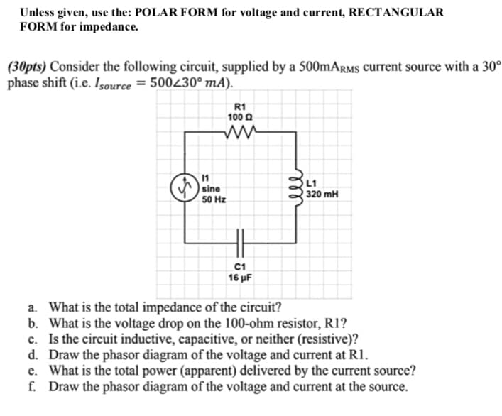
Transcribed Image Text:Unless given, use the: POLAR FORM for voltage and current, RECTANGULAR
FORM for impedance.
(30pts) Consider the following circuit, supplied by a 500mARMS current source with a 30°
phase shift (i.e. Isource=500230⁰ mA).
R1
100 Q
L1
320 mH
C1
16 μF
a. What is the total impedance of the circuit?
b. What is the voltage drop on the 100-ohm resistor, R1?
c. Is the circuit inductive, capacitive, or neither (resistive)?
d. Draw the phasor diagram of the voltage and current at R1.
e. What is the total power (apparent) delivered by the current source?
f. Draw the phasor diagram of the voltage and current at the source.
11
sine
50 Hz
ell
Expert Solution
This question has been solved!
Explore an expertly crafted, step-by-step solution for a thorough understanding of key concepts.

This is a popular solution!

Trending now
This is a popular solution!

Step by step
Solved in 3 steps with 3 images

Knowledge Booster


Learn more about
Need a deep-dive on the concept behind this application? Look no further. Learn more about this topic, electrical-engineering and related others by exploring similar questions and additional content below.Recommended textbooks for you
Introductory Circuit Analysis (13th Edition)
Electrical Engineering
ISBN:
9780133923605
Author:
Robert L. Boylestad
Publisher:
PEARSON

Delmar's Standard Textbook Of Electricity
Electrical Engineering
ISBN:
9781337900348
Author:
Stephen L. Herman
Publisher:
Cengage Learning

Programmable Logic Controllers
Electrical Engineering
ISBN:
9780073373843
Author:
Frank D. Petruzella
Publisher:
McGraw-Hill Education
Introductory Circuit Analysis (13th Edition)
Electrical Engineering
ISBN:
9780133923605
Author:
Robert L. Boylestad
Publisher:
PEARSON
Delmar's Standard Textbook Of Electricity
Electrical Engineering
ISBN:
9781337900348
Author:
Stephen L. Herman
Publisher:
Cengage Learning
Programmable Logic Controllers
Electrical Engineering
ISBN:
9780073373843
Author:
Frank D. Petruzella
Publisher:
McGraw-Hill Education

Fundamentals of Electric Circuits
Electrical Engineering
ISBN:
9780078028229
Author:
Charles K Alexander, Matthew Sadiku
Publisher:
McGraw-Hill Education

Electric Circuits. (11th Edition)
Electrical Engineering
ISBN:
9780134746968
Author:
James W. Nilsson, Susan Riedel
Publisher:
PEARSON

Engineering Electromagnetics
Electrical Engineering
ISBN:
9780078028151
Author:
Hayt, William H. (william Hart), Jr, BUCK, John A.
Publisher:
Mcgraw-hill Education,