For the circuit shown in Figure Q2, determine the followi (a) The current in the inductors L1 and L.2. (b) The voltage across the capacitors Cl and C2. (c) The total energy stored in the circuit. (d) The total power supplied by the source. 30V 1.1 RI -000-m 1052 50mH 20mH R2 2002 1.2 300µF 1.3 -000 CI 30ml 91 300µF 600 μF R3 3052 C3
For the circuit shown in Figure Q2, determine the followi (a) The current in the inductors L1 and L.2. (b) The voltage across the capacitors Cl and C2. (c) The total energy stored in the circuit. (d) The total power supplied by the source. 30V 1.1 RI -000-m 1052 50mH 20mH R2 2002 1.2 300µF 1.3 -000 CI 30ml 91 300µF 600 μF R3 3052 C3

Delmar's Standard Textbook Of Electricity
7th Edition
ISBN:9781337900348
Author:Stephen L. Herman
Publisher:Stephen L. Herman
Chapter24: Resistive-inductive-capacitive Parallel Circuits
Section: Chapter Questions
Problem 1RQ: An AC circuit contains a 24 resistor, a 15.9-mH inductor, and a 13.3F capacitor connected in...

Related questions

Question
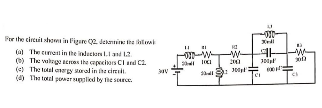
Transcribed Image Text:For the circuit shown in Figure Q2, determine the followi
(a) The current in the inductors L1 and L2.
(b) The voltage across the capacitors Cl and C2.
(c) The total energy stored in the circuit.
(d)
The total power supplied by the source.
30V
II
RI
-000-m
20mH
1052
50mH
2
R2
2002
300µF
-000
30ml
91
300µF
CI
600 μF
R3
30Ω
C3
Expert Solution
This question has been solved!
Explore an expertly crafted, step-by-step solution for a thorough understanding of key concepts.

Step by step
Solved in 6 steps with 4 images

Knowledge Booster


Learn more about
Need a deep-dive on the concept behind this application? Look no further. Learn more about this topic, electrical-engineering and related others by exploring similar questions and additional content below.Recommended textbooks for you
Delmar's Standard Textbook Of Electricity
Electrical Engineering
ISBN:
9781337900348
Author:
Stephen L. Herman
Publisher:
Cengage Learning
Delmar's Standard Textbook Of Electricity
Electrical Engineering
ISBN:
9781337900348
Author:
Stephen L. Herman
Publisher:
Cengage Learning