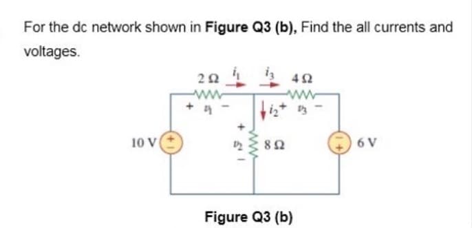
For the dc network shown in Figure Q3 (b), Find the all currents and voltages. 42 ww iz+ 3 10 V 82 6 V ww


Q: -A series generator dellvers a current of 90 A at 240 V. Its armature and series fleld resistances…
A:
Q: 1. Determine the currents and voltages across all the resistances indicated in the circuit shown in…
A: The above problem can be solved using either of the circuit theory mentioned below. They are:…
Q: For the dc network in Figure Q1(b) calculate the unknown voltages V2 and V1 using Kirchoff's voltage…
A:
Q: 1) For a circuit shown in Figure, |(a) find the currents I,, I, and I3. (b) find the potential…
A: The above given circuit can be solved using either of the circuit theory rules mentioned below:…
Q: (b) For a configuration as shown in Figure Q1(b), determine the current through 402 resistor, I40n-…
A:
Q: For a configuration shown in Figure Q4, determine the current through R, using THEVENIN theorem. R2…
A:
Q: (c) Using superposition theorem to determine the voltage Va in the network shown in Figure Q1(c).…
A:
Q: Q.28: For the circuit shown: V3-150cos500t Volt 1. Specify the numerical value of RL for maximum 500…
A:
Q: Determine the currents and voltages across all the resistances indicated in the circuit shown below.…
A: as per the guidelines, we supposed to answer one question at at time so please ask other question…
Q: Q2) Non – sinusoidal voltage applied on 102 resistance with consumed power 521.25 watts and the…
A: We need to find out current and effective voltage for given power .
Q: (a) In the AC circuit shown in Figure Q3a, determine the equivalent resistance between the terminals…
A: A given circuit is shown below. Find the equivalent resistance between A and B.
Q: 7. For the network in 'figure a. the short-circuit currents I, and I,. b. the voltages V, and V2. c.…
A: A resistance in parallel with short circuit is equivalent to Short i.e. zero resistance. So voltage…
Q: For the circuit shown in the figure, the power (p3) is: 8 V P4 3A P2 20 V P3 12 V Ps 0.41 O a.-138 W…
A: Compare the current in the right-most branch. 0.4I=3 AI=7.5 A
Q: n the circuit below, whatis thendde voltage/ Siven R1 = R2 = R3 = 60 N %3D %3D
A:
Q: Consider an electrical network shown in figure with load resistor, F 2.2kn 2.7kn w- R4 R1 R2 7kn…
A:
Q: - 8V For the network of Figure Q3, determine: a) In b) Ve c) Ver 2.2 k 1.8 ka +10V
A:
Q: QI U. UTMA) Based on electrical DC circuit as depicted in Figure QI(a). (i) UT Determine the mesh…
A:
Q: H.W. 3.8: Apply nodal analysis to find i, and the power dissipated in each resistor in the circuit…
A:
Q: Part3: Resistors connected in a combination of series and parallel The circuit shown below was…
A:
Q: Example: For the circuit shown in Figure below, use nodal analysis to determine the current through…
A: Consider the given circuit and the flow of currents. Let the voltage of node a is Va and for node b…
Q: H.W. In the network in Figure shown below, V. is known to be 8 45°V. Compute Vs: I3 -j2n I, V j2n 20…
A: In this question, We need to determine the voltage Vs If voltage Vo is given. We Vs= V1+jX Is
Q: 3.19 Determine V3 and Vs in the circuit shown in Figure P3.14. 9.00ka 7.00kO 3.00A 3.00kn 5.00ka V3…
A:
Q: 2. Given the circuit, R5 R3 2 kn R1 3 kn 1 kn + V1 R28 kn R427 kn R526 kn 111 V Applied Voltage…
A:
Q: Draw the AC equivalent circuit for the figure below: Please post the complete solution. NEED ANSWERS…
A:
Q: Q2:- Find the current I, and the voltage V, for the network in Figure shown below R 12 V R330 V; R E…
A: The solution can be achieved as follows.
Q: For a circuit shown in Figure, a) find the currents I,, I,, and I3. (b) find the potential…
A: Nodal analysis is a technique used to calculate the currents in all the paths. Kirchoff current law…
Q: b) For the circuit shown in Figure Q3b: i) Define coupling coefficient. ii) Find the voltage, Vx. j3…
A:
Q: Determine the value of ZL in the circuit of Figure Q3(a) for maximum power transfer.
A:
Q: Figure Q3 shows a voltage divider Field Effect Transistor (FET) network. Given VGsQ = 1.5 V, InDQ =…
A: Brief description: Field effect transistors one of the transistor where they can provide infinite…
Q: Q1\ Write the mesh equations for the circuit in figure below R www HE 4 Ω 8 Ω E₁10V 200 6Ω = E2₂ =…
A:
Q: Q) Using nodal analysis, find current i, and the power dissipated in the 4-ohm resistor in the…
A: In the circuit, Find the current io and power dissipated in the 4 ohm resistance. We are solving…
Q: Solve for the currents in various branches of the circuit shown in the figure below: V1= 50V; V2320V…
A: In this question, We need to determine the current in the branch. We are solved this problem using…
Q: 1) For a circuit shown in Figure, (a) find the currents I1, I2, and I3. (b) find the potential…
A: Nodal analysis is a technique used to calculate the currents in all the paths. Kirchoff current law…
Q: H.W. 2.3: Find the equivalent resistance of the network between the terminals A and B shown in the…
A: When same current flows the resistors , they are said to be in series. The net resistance is the sum…
Q: Refer to the DC network of Figure 3. The following data is applicable on the components in the…
A: As per the guidelines, we supposed to answer first three part of the question at a time so please…
Q: For the network of Figure Q2, calculate: (a) I, (b) In, (c) I2, (d) Vz- Express your answer in…
A: First calculate impedance of the inductor and capacitor. Now using ohms law find current I1 and I2…
Q: Solve for the currents in various branches of the circuit shown in the figure below: V1= 25 V; V2=…
A: Given circuit, V1=25 VV2=10 V
Q: R1 = 50 ohm R3 R2 RI R2 = 25 ohm I2 El = 5 volt R3 = 75 ohm E2 E2 = 4 volt [Q3] Analyze the…
A: Given values are = Given circuit is =
Q: Find the voltage 'V,' shown in the figure if R1 = 18 2, R2 = 7Q and R3 = 2 Q. R10 ww- 40 V R2Q V1 =
A: Given, The circuit is Here, R1=18 ΩR2=7 ΩR3=2 Ω
Q: 1) For a circuit shown in Figure, (a) find the currents I, I,, and lz. (b) find the potential…
A: We will assume voltage at node b as V and voltage at node a is zero as it is grounded. We will apply…
Q: A pure resistor in an AC circuit behaves in exactly the same way as in the equivalent of DC circuit.…
A: To find the current through bulb L3
Q: Determine the current through R₁ in figure below if Vs = 50 V +0- Vs A www R₁ 560 Ω R₂ 330 Ω R₂ 330…
A: Given circuit: Source voltage, Vs=50 V.
Q: (c) For the circuit shown in Figure Q2 (c).Determine i, to is. 122 ww is 600 V 16 2 |i4 82 |is 42…
A: Circuit simplified
Q: Find the attached file.
A:
Q: 1) For a circuit shown in Figure, (a) find the currents I, I,, and Iz. (b) find the potential…
A: To find the currents in each branch and potential difference between points a and b.
Q: + 6 V – P1 4 A P3 25 V (*) P4 10 V4)5Ix P5 P2
A: we have to find out the value of power supplied by the P4.
Q: For the dc network shown in Figure Q3 (b), Find the all currents and (b) voltages. iz 42 20 4 ww iz+…
A:
Q: For a circuit shown in Figure, (a) find the currents I,, I, and I3. (b) find the potential…
A: Given circuit,
Q: Q3) For the circuit shown in figure Q3, use Supermesh technique to calculate the current i, and the…
A:
Q: Q3) Determine the total current drawn by the circuit as shown in figure Q3. R1 = 15 2 R3 = 20 2 E…
A: If R1 and R2 are connected in series than equivalent resistance Req = R1 +R2. If R and R2 are…

Step by step
Solved in 3 steps with 2 images

- Use mesh analysis to determine the current supplied by each DC source in the circuit shown in the figure belowAn RLC series circuit connected to a 110 – volt and 50 – cycle AC source, contains the following series resistances and reactances: R1 = 10 ohm, R2 = 15, R3 = 5 ohms, XL1 = 20 ohms, XL2 = 25 ohms, XC = 40 ohms. Find the following: a.) EQUIVALENT REACTANCE b.) TOTAL IMPEDANCE c.) VOLTAGE DROP ACROSS THE CAPACITOR d.) TOTAL INDUCTANCE IN MILLIHENRY e.) TOTAL CURRENT f.) REACTIVE POWER g.) REAL POWER DRAW THE PHASOR DIAGRAM IF POSSIBLE AND ROUND OFF TO FOUR DECIMAL PLACESDiscuss why power plant and distribution system engineers are concerned a. with the real power absorbed by a load; b. with the reactive power.
- A 120-V rms 60-Hz source supplies two loads connected in parallel, as shown in the figure. a) Find the power factor of the parallel combination. b) Calculate the value of the capacitance connected in parallel that will raise the power factor to unity.Identify the equation that proves Kirchhoff's Voltage Law for the circuit below given the following:ES1 = 8 V, ES2 = 14 V, R1 = 12 Ω, R2= 10 Ω, R3 = 22 Ω, and IT = 0.5 AObjective 3 ) -Be able to calculate all forms of ac power in ac circuits with linear transformers and ideal transformers
- TOPIC: Ohm's Law, Power and Generating Direct CurrentDirect Current Circuit AnalysisInductor, Capacitor, Generating Alternating Current Please Answer in complete solution: V6 R45 R2345 Itotal I2 I1 VtotalANSWER SHOULD BE: V1 = 11.33V, V2 =26.67VSHOW THE STEP-BY-STEP SOLUTIONDefine 1 ?AC power, power factor and power triangle A series circuit has R=10 Ω, L= 50 mH and C= 100µF is supplied with 200V,50Hzsupply. Find (i) impedence (ii) current (iii) power(iv) power factor (v) voltage drop acrosseach element
- In the DC Circuits lab , "Ohm's Law", the resistance of the four load were measured and also their accepted values were calculated: For Load A: Resisitance=4.4 kΩ (accepted value) caluculated using formula =R= R1+ R2 + R3 Resisitance=4.42kΩ (experimental value) For Load B: Resisitance=0.47 kΩ (accepted value) caluculated using formula =R= 1/(1/R1+ 1/R2 + 1/R3) Resisitance=0.47kΩ (experimental value) For Load C: Resisitance=1.95 kΩ (accepted value) caluculated using formula =R= R1+(( R2*R3)/R2 +R3) Resisitance=1.95kΩ (experimental value) For Load D: Resisitance=1.08 kΩ (accepted value) caluculated using formula =R= ((R1+ R2)* R3)/R1+R2+R3 Resisitance=1.08kΩ (experimental value) Percent Discrepancy for each load were 0 What's the conclusion then?25/. A three phase loads each resistance of 100 Ω and capacitance of 10 µF are given, with 415 V, 50 Hz supply. Find the total power for i) Star Connection ii) Delta Connection iii) Draw and Compare your result for both the casesThe real power delivered by a source to two impedances, Z1=4+j5 and Z2=10 connected in parallel, is 1000 W. Determine (a) the real power absorbed by each of the impedances and (b) the source current.