Part3: Resistors connected in a combination of series and parallel The circuit shown below was generated on MapleSIM 2019 Voltmeler 1 Voltmeter 2 Ammeter 2 RI=250hms R2-500hms Ammeter 3 R3=75Ohms Voltmeter 3 V Ammeter Total 6V The simulated data is shown below, currents are in Amperes and voltages in Volts Arnalysis Winduw: Simulation Reults L Simulation Results D. K Probe Plots Stored Rasuts Ammeter 2i Ammeter 3i Ammeter Total i V Latest Resits 0 075 0.055 0 120 0050- 0.115 Vatubles MO.045 0.065 Find Mar K0.105 Stared Resut Seleced 0.060 0.035- 0.100 0.055 35 4 45 5 55 6 65 0.095 2 3 45 67 8 4. 4.5 35 Plot Windows: Cembeallon Veltmeter 1.v Valmte 2 73 Voleter 3y V Ammeter 2 U A eter 3 . meter Tetal 7. 4.5 Avotmeter 2e Vatreter 3 6.5 0.5 N 5.5 2.5 -0.5 10 10
Part3: Resistors connected in a combination of series and parallel The circuit shown below was generated on MapleSIM 2019 Voltmeler 1 Voltmeter 2 Ammeter 2 RI=250hms R2-500hms Ammeter 3 R3=75Ohms Voltmeter 3 V Ammeter Total 6V The simulated data is shown below, currents are in Amperes and voltages in Volts Arnalysis Winduw: Simulation Reults L Simulation Results D. K Probe Plots Stored Rasuts Ammeter 2i Ammeter 3i Ammeter Total i V Latest Resits 0 075 0.055 0 120 0050- 0.115 Vatubles MO.045 0.065 Find Mar K0.105 Stared Resut Seleced 0.060 0.035- 0.100 0.055 35 4 45 5 55 6 65 0.095 2 3 45 67 8 4. 4.5 35 Plot Windows: Cembeallon Veltmeter 1.v Valmte 2 73 Voleter 3y V Ammeter 2 U A eter 3 . meter Tetal 7. 4.5 Avotmeter 2e Vatreter 3 6.5 0.5 N 5.5 2.5 -0.5 10 10

Introductory Circuit Analysis (13th Edition)
13th Edition
ISBN:9780133923605
Author:Robert L. Boylestad
Publisher:Robert L. Boylestad
Chapter1: Introduction
Section: Chapter Questions
Problem 1P: Visit your local library (at school or home) and describe the extent to which it provides literature...

Related questions
Question
Already got part 1 only answer part 2
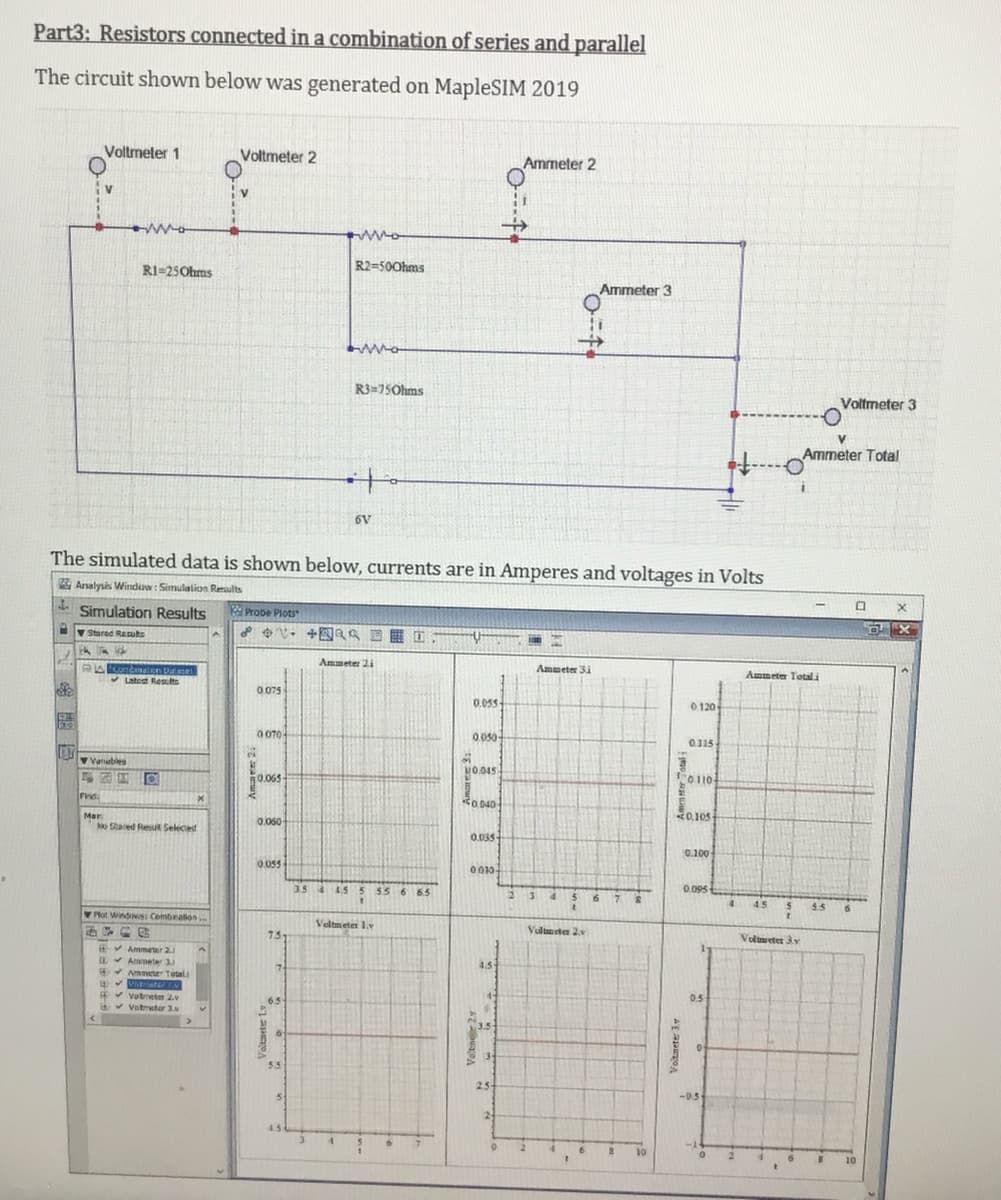
Transcribed Image Text:Part3: Resistors connected in a combination of series and parallel
The circuit shown below was generated on MapleSIM 2019
Voltmeler 1
Voltmeter 2
Ammeter 2
RI=25Ohms
R2=500hms
Ammeter 3
R3=75Ohms
Voltmeter 3
Ammeter Total
to
6V
The simulated data is shown below, currents are in Amperes and voltages in Volts
Analysis Winduw: Simulation Results
- Simulation Results
RProbe Plots
v Stared Resuts
Ammeter 2i
Ammeter 3i
Ammeter Total i
V Latest Reslts
0 075
0.05s-
0 120
0 070-
0.050-
0.115
2.
Vatubles
MO.045
0.065
O110-
Find
Ro 040
0,105
Mar
No Sared Resut Seleced
0.060
0.035
0.100
0.055
0010
3.5 4 45
5 55 6 65
2 34
56 7 S
0.095
4.
4.5
5.5
Plot Windows: Combealion.
Veltmeter 1.v
Valmeten 2v
73
Volmeter 3y
EV Ammeter 2.
Aameter 3.
* Ammeter Tetal
4.5
*votneter 2
v Votmeter 3.
0.5
5.5
2.5
-0.5
24
4.5
10
10
Voltnete 3
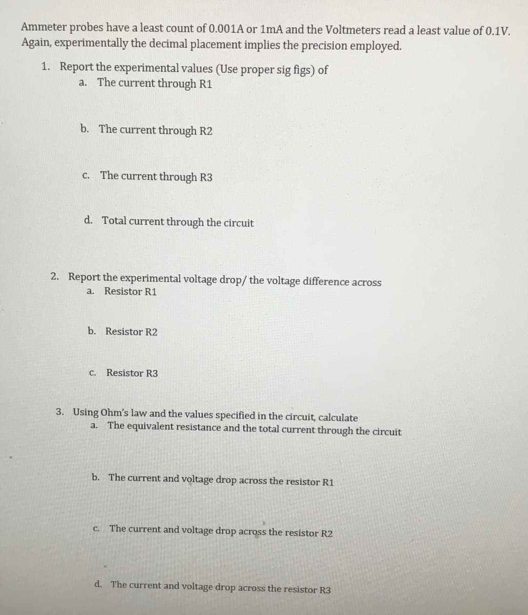
Transcribed Image Text:Ammeter probes have a least count of 0.001A or 1mA and the Voltmeters read a least value of 0.1V.
Again, experimentally the decimal placement implies the precision employed.
1. Report the experimental values (Use proper sig figs) of
a. The current through R1
b. The current through R2
c. The current through R3
d. Total current through the circuit
2. Report the experimental voltage drop/ the voltage difference across
a. Resistor R1
b. Resistor R2
C.
Resistor R3
3. Using Ohm's law and the values specified in the circuit, calculate
a. The equivalent resistance and the total current through the circuit
b. The current and voltage drop across the resistor R1
C.
The current and voltage drop across the resistor R2
d. The current and voltage drop across the resistor R3
Expert Solution
This question has been solved!
Explore an expertly crafted, step-by-step solution for a thorough understanding of key concepts.

Step by step
Solved in 2 steps with 3 images

Recommended textbooks for you
Introductory Circuit Analysis (13th Edition)
Electrical Engineering
ISBN:
9780133923605
Author:
Robert L. Boylestad
Publisher:
PEARSON

Delmar's Standard Textbook Of Electricity
Electrical Engineering
ISBN:
9781337900348
Author:
Stephen L. Herman
Publisher:
Cengage Learning

Programmable Logic Controllers
Electrical Engineering
ISBN:
9780073373843
Author:
Frank D. Petruzella
Publisher:
McGraw-Hill Education
Introductory Circuit Analysis (13th Edition)
Electrical Engineering
ISBN:
9780133923605
Author:
Robert L. Boylestad
Publisher:
PEARSON
Delmar's Standard Textbook Of Electricity
Electrical Engineering
ISBN:
9781337900348
Author:
Stephen L. Herman
Publisher:
Cengage Learning
Programmable Logic Controllers
Electrical Engineering
ISBN:
9780073373843
Author:
Frank D. Petruzella
Publisher:
McGraw-Hill Education

Fundamentals of Electric Circuits
Electrical Engineering
ISBN:
9780078028229
Author:
Charles K Alexander, Matthew Sadiku
Publisher:
McGraw-Hill Education

Electric Circuits. (11th Edition)
Electrical Engineering
ISBN:
9780134746968
Author:
James W. Nilsson, Susan Riedel
Publisher:
PEARSON

Engineering Electromagnetics
Electrical Engineering
ISBN:
9780078028151
Author:
Hayt, William H. (william Hart), Jr, BUCK, John A.
Publisher:
Mcgraw-hill Education,