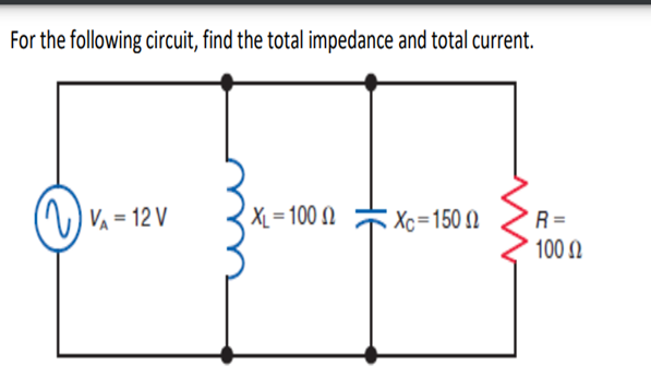
For the following circuit, find the total impedance and total current. VA - 12V XL=1002 Xc=1500 R= 100


Q: Find vo() for all t> 0 in the given circuit. Assume /= 6u(0) A 192 ΙΩ 7u(t) V ww ele www 1 H 0.5 F…
A: The given circuit isWe need to determine the expression of vo(t)=[A+(B)eCtD(Et+(F∘))]u(t) V.
Q: Figure #4 shows a series-parallel network with supply and output voltages Vs and Vo. V ΣΚΩ 333.33 μF…
A: Given that, A series parallel RLC circuit,Resistance, R1=2kΩResistance, R2=4kΩResistance,…
Q: An antenna array achieves beam steering in a direction of 30° from the normal propagation direction.…
A: Step 1:Step 2:
Q: Fill in the table using the input and output values(1,0). 5v A B 1k AND Gate D Y A B Output output 0…
A: Given:we need to fill the following table using input and output values.
Q: A household with electric resistance heating plans to switch from resistive heating to a ground…
A: To calculate the annual savings after switching from resistive heating to a ground source heat pump,…
Q: *4.19 The current source shown in the circuit of Fig. P4.19 is given by the displayed waveform.…
A: Solved below .Explanation:
Q: 1) For the expression f(A,B,C) = P0 + P5 + P6 + P7 , set the output in terms of one of the inputs…
A: Given the expression f(A,B,C)=P0+P5+P6+P7, where P0,P5,P6, and P7 are inputs to the…
Q: 3.The voltage across a 10 Q2 capacitive reactance is: v(wt) = 30 sin wt. a. What is the sinusoidal…
A: Given:voltage across 10-ohm capacitive reactance, we need to find:a) current expression through…
Q: Draw how an ASIC, SOC, MCU, MPU, DSP any TTL gates of the TTL circuits you have constructed or…
A: According to the question, we need to draw how an ASIC, SOC, MCU, MPU, DSP any TTL gates of the TTL…
Q: Calculate Vp using superposition
A: The given circuit isWe need to determine the voltage, Vp using superposition theorem.
Q: Task Using Transistor N22A, design and simulate using appropriate softw) C with lower catency of 500…
A: The objective of this question is to design and simulate a transistor amplifier circuit using a N22A…
Q: = 6.13 Obtain the model of the voltage vo, given the supply voltage v,, for the circuit shown in…
A: The given RC series circuit;Obtain the model of output voltage;
Q: An AC voltage sourced is connected to a series R= 250 ohm, L= 0.15H. The source has angular…
A: The objective of the question is to find the voltage amplitude for the source in an AC circuit with…
Q: Consider the circuit shown in (Figure 1). Suppose that C = 15.0 nF, L = 27.0 mH , and R = 74.0 Ω.…
A: Given:The objective is to find the following:(A) The oscillation frequency.(B) The time taken for…
Q: What is the Lock Out Tag Out system used by electricians?
A: The Lockout/Tagout (LOTO) system is a safety procedure used in various industries, including…
Q: A circuit is shown in the figure. C = 8x10⁴ F, L = 4×10² H, and R = 9 Q2. The AC source has a…
A: The circuit diagram is shown below,
Q: What precautions should a technician take when working specifically with or around electricty. Is…
A: When working with or around electricity, technicians should take the following precautions:1. Turn…
Q: Consider a point charge Q surrounded by two different materials. The properties of the materials are…
A: Please see the answer in explanation.Explanation:
Q: The process diagram of a binary power plant with an ORC-process, utilizing geothermal energy, is…
A: Turbine output power=191.48 KWExplanation:Step 1: Step 2: Step 3: Step 4:
Q: What are the principles behind electromagnetic interference (EMI) and methods to mitigate its…
A: Electromagnetic interference (EMI) occurs when electromagnetic radiation interferes with the regular…
Q: H.W: Design Op-Amp circuit to give the following output using 2 op-amps. Vo = -2V₁-3V2 + 4V3 +12V4 +…
A:
Q: Determine the (I) rms value up of the following waveforms: a)
A: In the given questions we need to calculate the RMS and average value of the following signal.
Q: The continuity equation shown below is used to derive the ideal current-voltage characteristic of a…
A: The objective of the question is to identify the true statements related to the continuity equation…
Q: "Electrical circuits/I need the expert's handwritten solution using equations for Z-paramedic."
A: “Since you have posted a question with multiple sub parts, we will provide the solution only to the…
Q: Question 2 = : Solve the below circuit using the Mesh-Current Method for R₁ = R2 = R3 = R4 = R5 R6…
A:
Q: 3. Use Nodal analysis to find (a) current flowing through all the branches in the following…
A: Given:withusing nodal analysis, we need to find:a) current flowing through all branches. b) power…
Q: A pure sinusoidal waveform with a period time or 0.02, has a frequency of 50Hz, define the angular…
A: The objective of the question is to calculate the angular frequency of a sinusoidal waveform…
Q: For ideal transformer n=2; Calculate I1, 12, V1, V2. 10/0° V 202 ΖΩ ww 1:2 Ideal ξίζΩ
A: Step 1:Step 2:Step 3:
Q: Find the steady state current across inductor when switch closed at f = 0
A: The given data is shown below:
Q: 8. In the circuit shown below, find: Vout (jw) a) Find H(jw) = 2.000 Ω ww Vin(jw) b) Determine the…
A: The given circuit isWe need to determine a. H(jω)=Vout(jω)Vin(jω) .b. The magnitude and angle of…
Q: 1. Given the DC Series Circuit below: R₁ = 30 kr m E=IVE M R₂ = 15k^ Mu R₂ = 60kλ a) Draw the DC…
A: Since you have posted a question with multiple sub parts, we will provide the solution only to the…
Q: ViA 24 M R 4702 25.5mA 12v IN4742A I Load max Ihmin Remin 12y 21mA ய RL 12v For The Zener To ? Stoy…
A: To ensure the Zener diode stays in regulation, we need to calculate the maximum and minimum current…
Q: 3. It is a remarkable fact that we can predict how a linear system responds to any input by just…
A: Step 1:Step 2:Step 3:Step 4:
Q: 1. Solve for the complex Power delivered to the Source.
A:
Q: determine the initial voltage across each component for the circuit below
A: The initial voltage across the 2Kohm resistor is V2Kohm=3.3333volts,The initial voltage across the…
Q: Obtain the transfer function Eo(s)/E(s) of the operational-amplifier circuit shown in Figure 6-91.…
A:
Q: Two parallel conductors carrying 200A of current and conductors are separated by 40mm. find the…
A: The given data is shown below:
Q: BO BO Wire BO 1 B B Metal rod d ━← Ⓡ B W
A: Current is flowing downwards.The didth of the metal rod is Find the voltage induce across the metal…
Q: (b) The transfer function of a digital control system is given by G(z) = z² - 1 (z 0.5)(z+0.2 +…
A: Given:transfer function of digital control system,we need to find:all the poles and zeros of the…
Q: Design an RLC network which, when placed in parallel with a 100 (2% tolerance) resistor, yields an…
A: This is a RLC circuit
Q: Info Consider the circuit shown below: R₁ ww WW R1 = 280 ohm R2 = 260 ohm R3 R = 590 ohm ·3 R4 2 =…
A: We are given,To determine the potential difference across R4 and power dissipated in R3
Q: Part A In the figure, the total resistance is 14.6 ks, and the battery's emf is 28.4 V. If the time…
A: An RC series circuit is a circuit that contains a resistor (R) and a capacitor (C) connected in…
Q: Obtain the transfer function E。(s)/E;(s) of the operational-amplifier circuit shown in Figure 6-91.…
A: The given data is shown below:
Q: Needs Complete solution with 100 % accuracy.
A: The objective of the question is to calculate the input power to a DC series motor powered by a…
Q: What is the steady-state current across R₁ in A given the supply voltage of 8 V is a applied at t=0?…
A: Given:with we need to find:the steady state current through resistance R1 when 8 V supply is applied…
Q: Use the superposition theorem to solve current flowing through 7 Ω
A: Step 1: Step 2: Step 3: Step 4:
Q: Pls answer the following and give proper solution and write it on a paper
A: To determine the unit variable cost, we calculate the difference between total costs and fixed…
Q: What assumption from the ideal diode derivation implies the following relation? qV bi/KT • P=P по ро…
A:
Q: Q4. Calculate io(t) for t> 0 in the network shown below. 2e 'u(t) V ΙΩ ww 1 F i 1 H m 4u(t) A ww 192
A: Given:a circuit,we need to determine current i0(t) for t>0.
Q: Design K that stabilizes the closed Loop system for K is constant (paregain) R(S) 5 S45-2
A:
For the following circuit, find the total impedance and total current.

Unlock instant AI solutions
Tap the button
to generate a solution
Click the button to generate
a solution
- An R-L series circuit contains two resistors and two inductors. The resistors dissipate powers of 96 watts and 125 watts. The inductors have reactive powers of 100 VARs and 78 VARs. What is the power factor?An R-L series circuit contains two resistors and two inductors. The resistors have values of 120 and 300 . The inductors have reactive values of 220 and 470 . Find impedance.7. The resistor in an R-L series circuit has a voltage drop of 53 V, and the inductor has a voltage drop of 28 V. What is the applied voltage of the circuit?
- A series RL with R = 88-Ω and L = 81-H connected across a 24 VDC source for a LONG TIME, what is the voltage across the inductor.For the circuit shown below calculate VS in V when IDSS=12mA VP=-6V and B=1201. In R-L-C series circuit if voltage across the circuit is reduced to half, what the changing in current will be? 2. If A positive angle of 143.13° what is the negative equivalent angle?
- A parallel circuit with the following parameters the total applied voltage is 150<-30. Current at branch one is 6.5<30. Current at branch two is 5<-53. Draw the phasor diagram of V-I and find the impedance of each branch and the total admittanceWhat is the equivalent resitance in Node DE?A series R-L circuit has a resistance of 20â ¦ and an inductive reactance of 15â ¦. What is the value of the circuit Z?