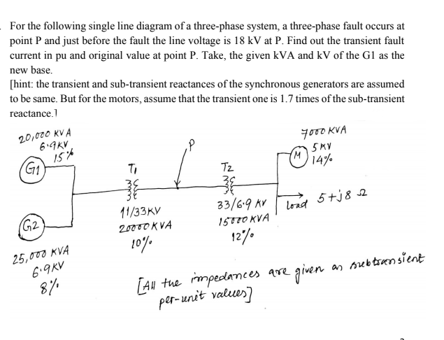
For the following single line diagram of a three-phase system, a three-phase fault occurs at point P and just before the fault the line voltage is 18 kV at P. Find out the transient fault current in pu and original value at point P. Take, the given kVA and kV of the G1 as the new base. [hint: the transient and sub-transient reactances of the synchronous generators are assumed to be same. But for the motors, assume that the transient one is 1.7 times of the sub-transient reactance.] 20,000 KV A 6.9KV yoo0 KVA G1 M 5KV Ti Tz 14% 33/6.9 AV 15570 KVA 12"% 11/33KV lond 5tj8 2 (G2 load 20000 K VA 10% 25,000 KVA 6.9KV [ạu tue mpedances are given [AN per-unit valeues) 8% as srebtrensient www
For the following single line diagram of a three-phase system, a three-phase fault occurs at point P and just before the fault the line voltage is 18 kV at P. Find out the transient fault current in pu and original value at point P. Take, the given kVA and kV of the G1 as the new base. [hint: the transient and sub-transient reactances of the synchronous generators are assumed to be same. But for the motors, assume that the transient one is 1.7 times of the sub-transient reactance.] 20,000 KV A 6.9KV yoo0 KVA G1 M 5KV Ti Tz 14% 33/6.9 AV 15570 KVA 12"% 11/33KV lond 5tj8 2 (G2 load 20000 K VA 10% 25,000 KVA 6.9KV [ạu tue mpedances are given [AN per-unit valeues) 8% as srebtrensient www

Power System Analysis and Design (MindTap Course List)
6th Edition
ISBN:9781305632134
Author:J. Duncan Glover, Thomas Overbye, Mulukutla S. Sarma
Publisher:J. Duncan Glover, Thomas Overbye, Mulukutla S. Sarma
Chapter7: Symmetrical Faults
Section: Chapter Questions
Problem 7.15P

Related questions

Concept explainers
Synchronous Generator
In comparison to an asynchronous generator, it is a machine where the rotor speed is equal to the rotating magnetic field produced by the stator, i.e., mechanical speed is equal to the electrical speed, thus called synchronous, and not asynchronous.
Salient Pole Rotor
Salient pole rotor includes a large number of exposed poles mounted on a magnetic wheel. The construction of a bright pole is as shown in the image on the left. The proposed poles are made of metal laminations. The rotor winding is provided on these poles and is supported by pole shoes.
Question
Transcribed Image Text:For the following single line diagram of a three-phase system, a three-phase fault occurs at
point P and just before the fault the line voltage is 18 kV at P. Find out the transient fault
current in pu and original value at point P. Take, the given kVA and kV of the Gl as the
new base.
[hint: the transient and sub-transient reactances of the synchronous generators are assumed
to be same. But for the motors, assume that the transient one is 1.7 times of the sub-transient
reactance.1
20,000 KV A
6.9KV
yo00 KVA
5MV
M
14%
Tz
33/6.9 AV
11/33KV
20000 KVA
10%
(G2
lond
5+j8 2
15770 KVA
12/.
25,000 KVA
6.9KV
8/%
as orebtransient
LAu tue mpedances are given
per-unit values)
Expert Solution
This question has been solved!
Explore an expertly crafted, step-by-step solution for a thorough understanding of key concepts.

Step by step
Solved in 2 steps

Knowledge Booster


Learn more about
Need a deep-dive on the concept behind this application? Look no further. Learn more about this topic, electrical-engineering and related others by exploring similar questions and additional content below.Recommended textbooks for you
Power System Analysis and Design (MindTap Course …
Electrical Engineering
ISBN:
9781305632134
Author:
J. Duncan Glover, Thomas Overbye, Mulukutla S. Sarma
Publisher:
Cengage Learning
Power System Analysis and Design (MindTap Course …
Electrical Engineering
ISBN:
9781305632134
Author:
J. Duncan Glover, Thomas Overbye, Mulukutla S. Sarma
Publisher:
Cengage Learning