
Concept explainers
Videos
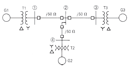
Equipment ratings for the four-bus power system shown in Figure 7.14 are as follows:
Generator G1: 500 MVA, 13.8 kV,
Generator G2: 750 MVA, 18 kV,
Generator G3: 1000 MVA, 20 kV,
Transformer T1: 500 MVA,
Transformer T2: 750 MVA,
Transformer T3: 1000Â MVA,
A three-phase short circuit occurs at bus 1, where the prefault voltage is 525 kV. Prefault load current is neglected. Draw the positive-sequence reactance diagram in per unit on a 1000-MVA, 20-kV base in the zone of generator G3. Determine (a) the Thévenin reactance in per unit at the fault, (b) the subtransient fault current in per unit and in kA rms, and (c) contributions to the fault current from generator G1 and from line 1-2.

Trending nowThis is a popular solution!

Chapter 7 Solutions
Power System Analysis and Design (MindTap Course List)


- Equipment ratings for the five-bus power system shown in Figure 7.15 are as follows: Generator G1:    50 MVA, 12kV, X=0.2 per unit Generator G2: 100 MVA, 15 kV, X=0.2 per unit Transformer T1: 50 MVA, 10 kV Y/138kVY,X=0.10 per unit Transformer T2: 100 MVA, 15 kV /138kVY,X=0.10 per unit Each 138-kV line: X1=40 A three-phase short circuit occurs at bus 5, where the prefault voltage is 15 kV. Prefault load current is neglected. (a) Draw the positive-sequence reactance diagram in unit on a 100-MVA, 15-kV base in the zone of generator G2. Determine (b) the ThĂ©venin equivalent at the fault, (c) the subtransient fault current in per unit and in kA rms, and (d) contributions to the fault from generator G2 and from transformer T2.arrow_forwardThévenin equivalent sequence networks looking into the faulted bus of a power system are given with ?1=?0.15 , ?2=?0.15 , ?0=?0.2and ?1=1∠0°per unit. Compute the fault currents and voltages for the followingfaults occurring at the faulted bus: (a) Balanced three-phase fault (b) Single line-to-ground fault (c) Line-line fault (d) Double line-to-ground fault Which is the worst fault from the viewpoint of the fault current?arrow_forwardDescribe the concept of fault current analysis in power systems and its role in protecting electrical equipment.arrow_forward
- As shown in Figure 1, a synchronous generator and motor are rated 100 MVA, 13.8 kV.??"=0.2per unit, ??"=0.15per unit, and ??=0.305per unit. The synchronous generator is operating at 100 MVA, 0.95 p.f. lagging and at 1.05 per unit voltage when a three-phase short circuit occurs atbus 2. Please use the direct method to calculate the per-unit values of (a)subtransient generator current (??"); (b)subtransient motor current (??"); and (c)subtransient fault current (??). Please use the superposition method to calculate the per-unit values of (d)subtransient generator current (??"); (e)subtransient motor current (??"); and (f)subtransient fault current (??).arrow_forwardTOPIC: Transmission Lines, Power Systems, and Powerplants:INSTRUCTIONS:- Answer in this format: Given, Illustration, Required Conversion, Solution, Final Answer.- Step-by-step solution, do not skip even simple calculations to avoid confusion.- If answered in written form, make sure it is readable.PROBLEM:The per-unit values of positive, negative, and zero sequence reactances of a network at fault are 0.08, 0.07, and 0.05 respectively. Determine the per-unit fault current if the fault is line-to-line-to-ground. j10 j12 j14 j16arrow_forwardLine to line to line fault is an asymmetrical type of fault in power system which occurs very frequently true falsearrow_forward
 Power System Analysis and Design (MindTap Course ...Electrical EngineeringISBN:9781305632134Author:J. Duncan Glover, Thomas Overbye, Mulukutla S. SarmaPublisher:Cengage Learning