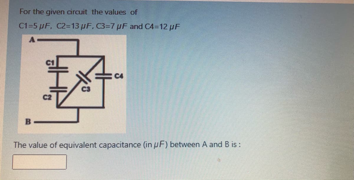
For the given circuit the values of C1=5 µF, C2=13 pF, C3=7 pF and C4=12 pF C4 C2 The value of equivalent capacitance (in pF) between A and B is:


Q: For the given circuit the values of C1=6 µF, C2=14 UF, C3=5 uF and C4=100 µF : C3 B The value of…
A:
Q: Capacitor dvc ic = C- Inductor dil VL = L Resistor VR = İRR %3D dt dt 115F 3SH
A:
Q: For the given circuit the values of C1=9 µF, C2=11 µF, C3=9 µF and C4=11 µF A C1 С4 C3 C2 В The…
A: Equivalent Capacitance between A-B CT= 24.95 micro Farad
Q: C1 3 µF C4 4.5 µF .C2 1 µF C5 +v1 500 V 4.5 µF C3 1 µF C6 4.5 µF C7 4.5 uF
A: Capacitor is an electrical component used to store electrical energy in the form of charge. It…
Q: 111. A capacitor bushing forms arm ab of a Schering bridge and a standard capacitor of 500 pF capa…
A:
Q: or the following RLC circuit, powered by a direct current voltage source of! 0 V, answer with V or F…
A:
Q: For the circuit in Figure 1, R = 2k2, L= 250MH, and C= 101F. The initial current in the inductor, is…
A: Apply KCL at node and than write the differential equation relating inductor current. Capacitor…
Q: The equivalent capacitor (Ceq) for the shown circuit is equal to: 4 mF ImF ImF (3 mF 5 mF b. 2 mF…
A:
Q: -In the circuit below Ci =5.0 µF, C2 = 6.0 µF, C3 =9.0 µF, and V 20 V. Find (Show work) a)…
A:
Q: The equivalent capacitance at terminals a-b in the circuit given is 30 F, then the value of C is a o…
A:
Q: For the circuit below, the initial inductor current i(0) is equal to 4 Amp. Find i(t) for t>0. + 4H…
A: The given circuit is source free RL circuit. It is given that the initial current flowing through…
Q: 1. Capacitors Cı=Co and C2-C/3 are charged as a parallel combination across a battery of Itage Vo.…
A:
Q: (d) Find vc() and in(). (d) Find the energies in the inductor and capacitor at t = 0, wi(0) and…
A:
Q: For the given circuit the values of C1=6 µF, C2=14 µF, C3=6 µF and C4=11 µF A C4 C3 C2 B The value…
A: In this question, we will find equivalent capacitance between A and B..
Q: IN THE CIRCUIT BELOW, AFTER THE CONDITION OF STATIONARY STATE (TIME > 5*TIME CONSTANT), THE VOLTAGE…
A:
Q: A charge and discharge RC circuit is composed of a resistance R and a capacitance C = 0.1µF. a)…
A:
Q: 2) It is required to use a capacitor with Vms = 12V. Select a suitable voltage rating capacitor from…
A: Capacitance can charge upto the Vmax of the input supply during charging stage Capacitance selection…
Q: 1. Find the equivalent capacitance across the terminals of the circuit in figure below 2.7 uF 2.7 uF…
A:
Q: • C1 = 3µF, C2 = 6µF capacitors are connected in series to a 15V DC voltage source. Eind the…
A:
Q: A 1ko resistor, a 142mH coil and a 160uF capacitor are all connected in parallel across a 240V, 60Hz…
A: Drawing the parallel RLC circuit:
Q: Q3: Impulse generator has 12 stages and contains 0.24 µF capacitors, the wave front resistance is 95…
A: An impulse generator is a device that generates extremely brief high voltage or high- current…
Q: The capacitor in the circuit is set to 1 F and the inductor is 9 H. HE + Vc 3u(-t) A ( , ) 12 -2i,…
A: At steady state capacitor acts as open circuit and inductor acts as short circuit. Capacitor does…
Q: Q3/ Find the equivalent capacitance. SuF 3µF HE HE AO 2uF 6uF 2µF 6µF HE HE 12µF BO
A: The given circuit is,
Q: For C1=8, C2=15, C3=34, C4=55, C5=49, C6=42, C7=81, C8=17 & C9=15 in the circuit shown below, Find…
A:
Q: The output voltage vo(t) across the parallel connection of the capacitor and a 20 resistor, the…
A:
Q: a. Sketch the root locus of the system shown in Figure Q8 when K varies from 0 to ∞. b. Determine…
A:
Q: Find the equivalent capacitance between points A and B of the given circuit 3.5 uF 5.0 μΕ 8.0 µF 1.5…
A: The equivalent capacitance can be calculated by reducing the parallel and series connected capacitor…
Q: di/dt in second order circuit has calculated from the * .voltage across inductor vL False True O
A:
Q: The circuit elements in the circuit are R=200 Ω, L=50 mH, and C=0.2 μF. The initial inductor current…
A:
Q: 5. Obtain the equivalent capacitance of the circuit below. 40 μF 35 μF 5 μF HH Q 10 μF 10 με HH 20…
A:
Q: 4. Calculate the energy stored in the capacitor network in the figure below when the capacitors.are…
A: The Capacitor is a charge storage element. When a power supply is connected to the capacitive…
Q: If the equivalent capacitor Ce=8 F when viewed from the AB terminals in the circuit given below,…
A: Option C is correct. The detailed solution is provided below.
Q: The equivalent capacitance at terminals a-b in the circuit given is 30 F, then the value of C is a o…
A: equivalent capacitance in series connection , 1Ceq=1C1+1C2+........equivalent capacitance in…
Q: 3. Find the equivalent capacitance of the group of capacitors shown in the circuit below. 15.00 μF…
A: Given,
Q: An RC circuit is comprised of a 1 k2 resistor and a 1,000µF capacitor. Assume a 1V source is applied…
A: In this question, RC circuit where R= 1k ohm and capacitance C= 1000uA are connect to 1V battery…
Q: For the circuit as shown below, find a single equivalent capacitor at terminals (a, b), where…
A:
Q: For the circuit shown in the Figure, if C1= 12 µF and C2= 35 uF, the equivalent capacitance is: C2…
A: In this question we need to find a equivalent capacitance for the given circuit
Q: 9. Determine the time constant of an RL circuit with a resistance R = 1.5 kohms and a 50mH inductor…
A:
Q: The equivalent capacitance at terminal in the circuit given is 30 F, then the valu C is а a o- = 14…
A: In this question , we have to find unknown capacitance...
Q: 2. If the circuit has a resistance R is 100 the inductor L is .5H and the capacitor C is 5 µf what…
A:
Q: 3. For an RC circuit comprising a capacitor C= 2 µF in series with a resistance R- 1 M2 , the period…
A:
Q: C1=5 µF, C2=10 µF, C3=9 µF and C4=14 uF C1 С4 C3 C2 B The value of equivalent capacitance (in µF)…
A: In this question we will find equivalent capacitance between A and B...
Q: Three capacitors, C1 = 5 µF, C2 = 10 µF and C3 = 20 µF are connected in parallel across a 150-V…
A:
Q: In the following circuit if C1 = 5 µF, C2=8μµF and C3 = 10 µF calculate equivalent capacitance of…
A: Given, C1=5 μFC2=8 μFC3=10 μF
Q: c) Solve the value of ve, il and the energy stored in the capacitor and inductor in thecircuit of…
A:
Q: oblem 4: alculate the step response to the system described by the linear uation depicted below:…
A:
Q: Determine the admittance of the below circuit looking at terminal a and b. Coverage: Basic RLC…
A:
Q: The 4 nF capacitors are pre-charged to 3 V, and the 10 nF capacitor is pre-charged to 1.2 V At t = 0…
A: According to the question we have to calculate the value of the final voltage.
Q: For the circuit as shown below, find a single equivalent inductor at terminals (a, b), where L1=17…
A:


Step by step
Solved in 2 steps with 2 images


- You are an electrician working in an industrial plant. You discover that the problem with a certain machine is a defective capacitor. The capacitor is connected to a 240-volt AC circuit. The information on the capacitor reveals that it has a capacitance value of 10 mF and a voltage rating of 240 VAC. The only 10-mF AC capacitor in the storeroom is marked with a voltage rating of 350 WVDC. Can this capacitor be used to replace the defective capacitor? Explain your answer.Consider the circuit below. a) Calculate the equivalent capacitance Ceq (show all steps) b) What is the potential difference across C4?Solve for the (and refer to the image): - individual voltages - individual charges wherein Equivalent capacitance of the capacitor is 0.76 F Charge stored in the circuit is 45.50 C. And V= 60V
- Capacitance= 4uF , Hence time constant is 5.33μs For the capacity value, calculate the estimated time to come to the final state.Plot capacitor current and voltage graphs and show if it works in harmony with the time constant you calculated. NOTE: if you want you can use falstad online circuit simulator.The circuit shown in the attached image contains a voltage source with emf ε = 2.99 V, a resistor with resistance R = 135 kΩ, and a capacitor with capacitance C = 612 nF. When switch S is set to position a, the three circuit elements are in series. When the switch is in position b, the battery is excluded from the circuit. The switch is initially moved to position a, where it remains for a sufficiently long time that the capacitor is fully charged. The switch is now moved to position b. What is the magnitude of the instantaneous current, in amperes, through the resistor the instant the switch makes contact with terminal b? With time meausred the instant that switch S is closed in position b, calculate the time, in seconds, when the charge on the capacitor is one-half of its maximum value. Calculate the current through the resistor, in amperes, at time t = 155.5 ms after the switch is closed in position b.An inductor of 5H, a resistor of 20ohms, and a capacitor of 20mF are connected in series with a source of E=10cos2t V. At t=0, the charge on the capacitor and current in the circuit is zero. Find the charge and current at any time t.
- Capacitance= 4uF2) Determine the time constant of the circuit for the capacities 3) For the capacity value, calculate the estimated time to come to the final state.4) Plot capacitor current and voltage graphs and show if it works in harmony with the time constant you calculated. NOTE: if you want you can use falstad online circuit simulator.You are given 10 resistors that are each 30 Ω. Construct a circuit with a resistance of exactly85 Ω. don't use all 15 resistors.a.) Explain process in designing the circuit.b.) Draw a diagram of the circuit,c.) Show that the total resistance for the circuit is 85Ω.d.) Suppose capacitors was given instead. Draw a circuit using 15 or fewer30 μ F capacitors, so that the circuit has a total capacitance of 85μF. Briefly explain the process.e.)Show that the total capacitance is 85μF.How can four 100 kΩ resistors be connected so that the equivalent resistance of the four equals 250 kΩ? Sketch the arrangement, describe the resistor arrangement in words, and justify your picture by calculating the equivalent resistance. Repeat this part of the question with four 100 F capacitors and an equivalent capacitance of 75 F.
- What is a Linear Circuit? Simply we can say that the linear circuit is an electric circuit (Links to an external site.) and the parameters of this circuit are resistance, capacitance, inductance and etc are constant. Or we can say the parameters of the circuits are not changed with respect to the voltage and current is called the linear circuit. What is a Non-Linear Circuit? The non-linear circuit is also an electric circuit and the parameters of this circuit differ with respect to the current and the voltage. Or in the electric circuit, the parameters like waveforms, resistance, inductance and etc are not constant is called as Non- linear circuit. Question: Is it possible to apply superposition theorem to nonlinear circuit? If yes, why? and if no, why?Capacitance’s of 15μF, 12μF, 17μF, and 19μF are connected in parallel to a Direct Voltage Supply of 400V. Determine the: (A) Equivalent Circuit Capacitance, (B) Total Charge, and (C) Charge on each Capacitor.6.27 Given that four capacitors can be connected inseries and in parallel, find the minimum andmaximum values that can be obtained by suchseries/parallel combinations.....