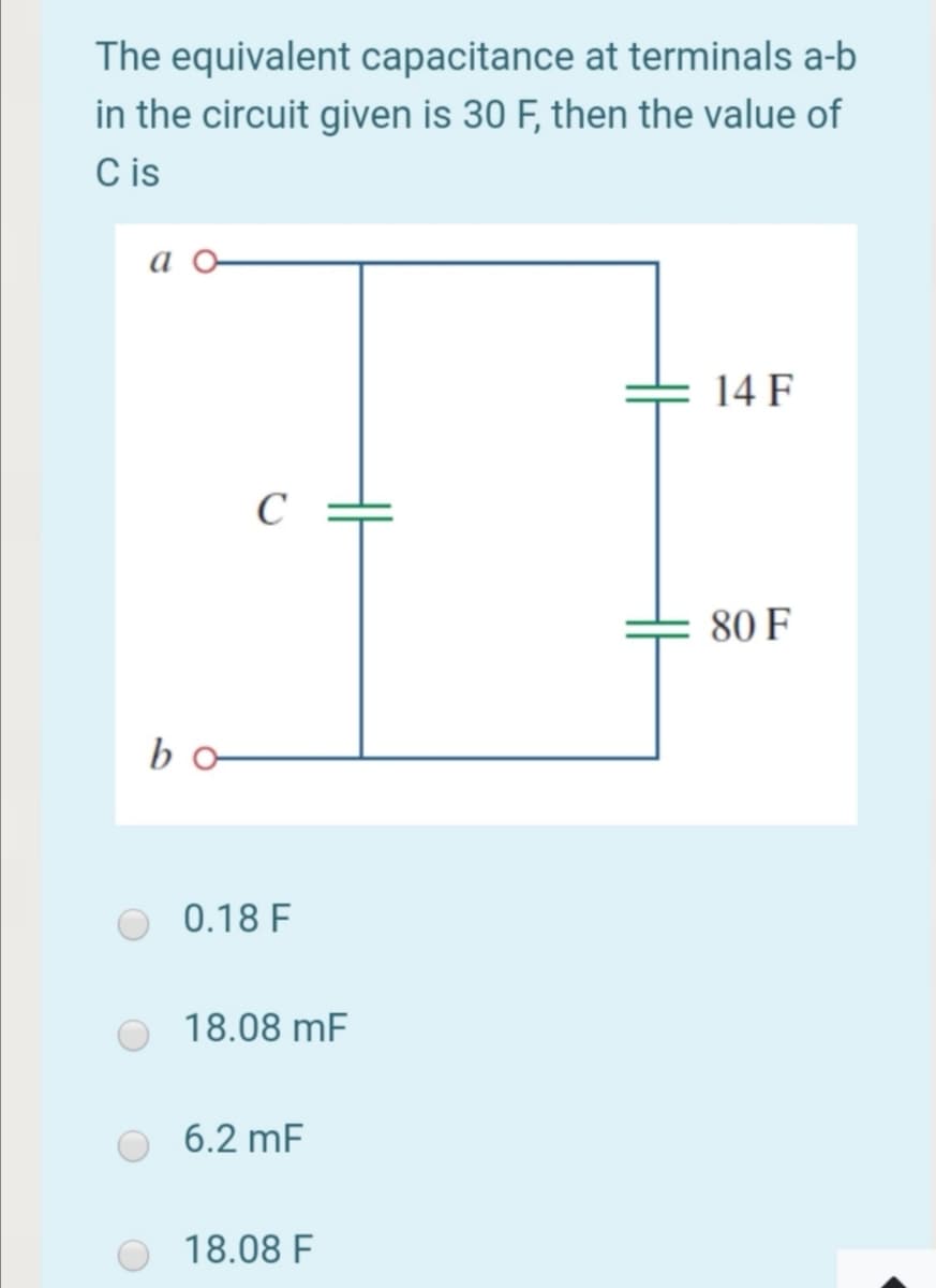
The equivalent capacitance at terminal in the circuit given is 30 F, then the valu C is а a o- = 14 C 80 bo


Q: When the switch is closed at t=0, obtain the inductor current for t > O in the circuit * shown in…
A: From the First order Transients
Q: The equivalent capacitance at terminals a-b in the circuit given is 80 F, then the value of C is
A:
Q: 2. A 0.5uF capacitor has voltage waveform v(t) as shown in following figure, plot i(t) as function…
A:
Q: A 750-ohm resistor, an uncharged 1.50 uF capacitor, and a 8.00-V emf are connected in series. (a)…
A:
Q: t=0 s 12- 3Α 10Ω 10Ω .(t)0.1F O A) 5V Ο Β) 8V C) ov Ο D 15ν Ο Β 10V
A: In an electric circuit, the transients are due to energy storing elements. If the network contains…
Q: In the following circuit, swith was in position a for longtime, what will be the capacitor current…
A: The switch has been at position (a) for long time.
Q: Find the time constant and initial current, i(0), through the inductor. t = 0 12Ω 8 15 A i(t) 24 2 2…
A: Given circuit,
Q: The circuit below has the following parameters:ß =120 , r, = 300 k2 ,r, = 502 ,C, =1pF,C, =1.924PF…
A: The cutoff frequency is a critical property of any filtering circuit, such as RC circuits. The…
Q: If we replace the segment marked with an "S" in Figure above with a 100 uf capacitor, the total…
A: Answer: True The equivalent capacitance connected in series is calculated by using the formula…
Q: 4. A) Reduce the given circuit to the fewest possible components thru series/parallel combinations…
A: The reduced circuit can be obtained by considering the parallel and series connected elements. The…
Q: • C1 = 3µF, C2 = 6µF capacitors are connected in series to a 15V DC voltage source. Eind the…
A:
Q: When the switch is closed at t=0, obtain the inductor current for t > O in the circuit * shown in…
A: At t=0-, the circuit becomes, Calculate the inductor current: i(0-)=2×44+4=1 A
Q: When the switch is closed at t=0, obtain the inductor current for t > O in * the circuit shown in…
A: We will try to solve the problem using the properties of inductance and the conditions of the…
Q: The current through a 0.8-F capacitor is 15(1-e-t ) A. Determine the voltage at t = 6. Assume v(0) =…
A: Given : In the given question they have mentioned the value of current flowing through a capacitor.…
Q: The capacitor in the circuit is set to 1 F and the inductor is 9 H. HE + Vc 3u(-t) A ( , ) 12 -2i,…
A: At steady state capacitor acts as open circuit and inductor acts as short circuit. Capacitor does…
Q: 13. Two capacitors C1= 50 µF and C2 = 30 µF are connected in series. Find the equivalent capacitance…
A:
Q: Which of the following is true for the given circuit? I. The starting currents in both inductors are…
A:
Q: i(t) = 3-4.5e6f A for t>0 2.5 H + v(t) i(t)
A: This question comes from circuit theory. By using formula of voltage across inductor , this can be…
Q: The following circuit corresponds to: Time left 0:51 Ic(s)→ 2/s Vc() + 2/s a 2F capacitor with an…
A: For DC supply , capacitor acts as open circuit and inductor acts as short circuit. First assume the…
Q: Find the equivalent capacitors seen between terminals a and b of the circuits 60 μF 20 μF 6 µf 20 μF
A: To solve above problem, one should know how to find equivalent resistance for series and parallel…
Q: Analyze a series R.L.C. circuit consisting of 40 resistor, 22.5 H inductor and a capacitor with 200V…
A: According to question:
Q: In a series RLC circuit, the resistance is 200 Q, the inductance is 10mH, and the capacitance is 4…
A:
Q: At s = 0, the admittance of the inductor is zero meaning the inductor looks iike a short circuit.…
A: At s=0 the impedance of inductor in s-domain is given as: Z(s)=sL The admittance is given as:…
Q: The shown circuit is connected for a very long time with all capacitors were initially unchargod.…
A:
Q: If the equivalent capacitor is Ce=7.5 F when viewed from the AB terminals in the circuit given…
A:
Q: Find the equivalent capacitance between points A and B of the given circuit 3.5 uF 5.0 μΕ 8.0 µF 1.5…
A: The equivalent capacitance can be calculated by reducing the parallel and series connected capacitor…
Q: di/dt in second order circuit has calculated from the * .voltage across inductor vL False True O
A:
Q: 5. Obtain the equivalent capacitance of the circuit below. 40 μF 35 μF 5 μF HH Q 10 μF 10 με HH 20…
A:
Q: + -5 (sui)7 5. 10- suu d = Copacitor is shown in the figure. Find the
A: we need to find the energy stored in the capacitor for various time instant given in the circuit.
Q: Determine the equivalent capacitance at terminals a-b of the circuit. 4 μF 6 µF 5 μ. 12 µF 3 μF 2 µF…
A:
Q: If the equivalent capacitor Ce=8 F when viewed from the AB terminals in the circuit given below,…
A: Option C is correct. The detailed solution is provided below.
Q: The equivalent capacitance at terminals a-b in the circuit given is 30 F, then the value of C is a o…
A: equivalent capacitance in series connection , 1Ceq=1C1+1C2+........equivalent capacitance in…
Q: How many microfarads is the equivalent capacitor value when viewed from the ab ends of the circuit…
A: According to the question we have to find the value of the equivalent capacitance.
Q: The capacitor in the circuit is set to 1 F and the inductor HE + Vc 3u(-t) A ( 4 ) 12 -2i, ell +,
A: given circuit
Q: 3. A 50µF capacitor is connected in parallel with a 20µF capacitor and the combination is placed…
A: In this question parallel combination of capacitors is given...We have to find out total capacitance…
Q: 2. If the circuit has a resistance R is 100 the inductor L is .5H and the capacitor C is 5 µf what…
A:
Q: 9-Determine the equivalent capacitance at terminals a-b of the circuit below. 5 µF 6 µF 4 μF H 2 µF…
A:
Q: 16. Find the equivalent capacitance at terminal a-b O 31.187 µF O 32.187 µF O 33.187 µF O 34.187 µF
A: In this question, choose the correct options Total equivalent capacitance across the terminal a and…
Q: In the following circuit if C1 = 5 µF, C2=8μµF and C3 = 10 µF calculate equivalent capacitance of…
A: Given, C1=5 μFC2=8 μFC3=10 μF
Q: Find v(t) on Capacitor and upload your solution* at t=0 10 2 12 0 2 F | 12 V 10 2 +1
A: Draw the circuit for t < 0.
Q: 1. Find the voltage of each capacitor as a function of time. Initial capacitor voltages are zero at…
A: Given circuit shown with a=3b=9c=7d=9
Q: The current through a 0.8-F capacitor is 7(1-e-t ) A. Determine the voltage at t = 9. Assume v(0) =…
A: The current through a 0.8-F capacitor is 7(1-e-t ) A , Assume v(0) = 11 Here we have to Determine…
Q: Find the total equivalent capacitance.(C1 = 1 F, C2 = 2 F, C3 = 3 F, C4 = 12 F)
A:
Q: 22 41 The capacitor in the circuit of Figure below is initially uncharged. Find vo(t) for t>0. 58(0)…
A:
Q: Find the inductor current iL(t) in time interval 0 <t s1 for the circuit given in the figure. R = 4…
A:
Q: A voltage source of 10 V is connected to a series RC circuit where R=2*10^6 ohms and c=3…
A:
Q: The switch in the figure below is closed at t = 0. The initial voltage on the capacitor is ve(0) =…
A: In this question , we will find. Capacitor voltage after switch close...And current is…
Q: The capacitor in the circult of Figure below is Initially uncharged. Find vo) for t> 0. 550) V , IF
A:
Q: A 0.33- uF capacitor is in parallel with a 0.15 uF and a 220,000-pF capacitor. What is the total…
A:

Step by step
Solved in 2 steps with 1 images


- Assume that the voltage drop across the resistor, ER, is 78 V, that the voltage drop across the inductor, EL, is 104 V, and the circuit has a total impedance, Z, of 20 . The frequency of the AC voltage is 60 Hz. ETITZ20VAPFER78VIRRPEL104VILXLVARsLLA LC circuit in a radio tuned to 1080 kHz has an inductor with an inductance value of 60 μH and a resistance of 0.25 Ω. a. what is the capacitance of the LC circuit? b. sketch the impedance phasor diagram for the radio. Be sure to label important features of the diagram.An RLC series circuit contains an unknown capacitor, an inductor with an inductance of 40 mH, and a resistor with a value of 16 Ω. The circuit is connected to a 240-V, 60-Hz line. If a current of 8 A flows in the circuit, determine the value ofthe unknown capacitor? Show your work. a) 2.575 uF b) 25.75 uF c) 257.5 uF d) 2575 uF
- A 200 Ω resistor, 0.900 H inductor, and 6.00 µF capacitor are connected in series across a voltage source that has voltage amplitude 30.0 V and an angular frequency of 250 rad/s. (a) What are v, vR, vL, and vC at t = 20.0 ms? Compare vR + vL + vC to v at this instant. (b) What are VR, VL, and VC? Compare V to VR + VL + VC. Explain why these two quantities are not equal.An amateur radio operator wishes to build a receiver thatcan tune a range from 14.0 MHz to 15.0 MHz. A variablecapacitor has a minimum capacitance of 86 pF. (a) Whatis the required value of the inductance? (b) What is themaximum capacitance used on the variable capacitor?The voltage across a 100-μF capacitor takes thefollowing values. Calculate the expression for thecurrent through the capacitor in each case.a. vC(t) = 40 cos(20t − π/2) Vb. vC(t) = 20 sin 100t Vc. vC(t) = −60 sin(80t + π/6) Vd. vC(t) = 30 cos(100t + π/4) V
- A circuit is designed with an AC source of max voltage 12 and frequency 60 Hz. The circuit has a resistance of 1050 Ohms, an inductance of 0.06 Henrys, and a capacitance of 0.009 coulombs per volt. - omega for source in rad/s? - omegaR for circuit? -XL? -XC? -phi in radians? -Z? -imax?an ac source of emf 5.0 v is connected to a series rlc circuit at a phase angle of 33 degree. find the potential across the capacitor when the magnitude of potential difference across the inductir reaches the macimum value of 6 v.What is incorrect about the RLC AC Circuit shown? 1 The power dissipation through the (ideal) capacitor is vanishing. 2 The current leads the voltage across the capacitor by 90deg. 3 The voltage across the inductor leads the current by 90deg. 4 If the AC source is replaced by a constant DC source, after a very longtime, the voltage across the inductor vanishes. 5 If the AC source is replaced by a constant DC source, after a very longtime, the voltage across the capacitor will be equal to that across theresistor.
- An RL circuit with a 8-ohm resistor and a 0.08-H inductor carries a current of 1 A at t = 0, at which time a voltage source E(t) = 8 cos (90t) V is added. Determine the subsequent inductor current and voltage.The capacitor of external defibrillator must be loaded at 1500V, in order to generate a two-phase wave of 150 J.Considering a transthoracic impedance is 80ohms and a capacitance of 30 000 uF. 3- What is the energy of the capacitor?4- What is the internal impedance of the defibrillator in the previous cases?An ac circuit includes a 155 Ω resistor in series with a 8.00 μF capacitor. The current in the circuit has amplitude 4.00×10⁻³ A. At the frequency for which the capacitive reactance equals the resistance, find when the voltage across the resistor is maximum, what is the voltage across the capacitor? When the voltage across the capacitor is maximum, what is the voltage across the resistor?