For the given circuit the values of C1=8 µF, C2=13 µF, C3=8 µF and C4=12 µF A C1 C3 C2 C4 B. The value of equivalent capacitance (in µF) between A and B is:
For the given circuit the values of C1=8 µF, C2=13 µF, C3=8 µF and C4=12 µF A C1 C3 C2 C4 B. The value of equivalent capacitance (in µF) between A and B is:

Delmar's Standard Textbook Of Electricity
7th Edition
ISBN:9781337900348
Author:Stephen L. Herman
Publisher:Stephen L. Herman
Chapter19: Capacitors
Section: Chapter Questions
Problem 1PP: Fill in all the missing values. Refer to the formulas that follow. Resistance Capacitance Time...

Related questions

Question
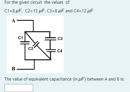
Transcribed Image Text:For the given circuit the values of
C1=8 µF, C2=13 µF, C3=8 µF and C4=12 µF
A
C1
C3
C2
C4
B.
The value of equivalent capacitance (in µF) between A and B is:
Expert Solution
This question has been solved!
Explore an expertly crafted, step-by-step solution for a thorough understanding of key concepts.

Step by step
Solved in 2 steps with 2 images

Knowledge Booster


Learn more about
Need a deep-dive on the concept behind this application? Look no further. Learn more about this topic, electrical-engineering and related others by exploring similar questions and additional content below.Recommended textbooks for you
Delmar's Standard Textbook Of Electricity
Electrical Engineering
ISBN:
9781337900348
Author:
Stephen L. Herman
Publisher:
Cengage Learning
Delmar's Standard Textbook Of Electricity
Electrical Engineering
ISBN:
9781337900348
Author:
Stephen L. Herman
Publisher:
Cengage Learning