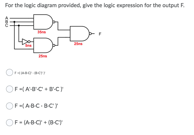
For the logic diagram provided, give the logic expression for the output F. 35ns 25ns 5ns 25ns F-( (A-B-C)' · (B-C')' Y


Q: For the Logic circuit shown below, A B Find Expression for F Simplify the expression of F using…
A:
Q: Show the Ladder logic program and the equivalent Function Block Diagram for the following Boolean…
A:
Q: Build the logic circuit for the function F1 = XYZ + YŽ + YZ using PAL
A:
Q: Draw the logic circuit that represents the following Boolean expression: AB(C + D)
A:
Q: Find the output Q of the logic circuit shown in below, for inputs shown below A= 110011 B-010101
A: A combinational circuit is one in which the various gates in the circuit, such as the encoder,…
Q: Draw the logic diagram for the Boolean expression Y = A.B.D + B.C.D+
A:
Q: 1- Write Demorcan's first law for three entrances with drawing the logical circuit and achieving the…
A: Please find the detailed solution in below images
Q: Simplify the given Boolean expression and draw the logic diagram for the solution.
A: GIVEN BOOLEN EXPRESSION AB+ A(B+C) +B(B+C) AB+ AB+AC +BB+BC AB +AC+B+BC Simplified BOOLEN EXPRESSION…
Q: Q. 1 Implement the logic circuit for the following expression of Y. Y = Ā.B + C.B
A: As per the guidelines of Bartleby we supposed to answer first question only.
Q: What is the Boolean expression for the logic circuit shown? A B O A. ABC + BC +AB O B. AB + B(B+C) +…
A: If A and B are inputs to OR gate than output ot OR gate A+B. If A and B are the AND gate than output…
Q: 22. A manufacturing process is controlled by a built in logic circuit which is made up of AND, OR…
A:
Q: (1) Find out the logic expression of output Q for the circuit on the left. And prove this is…
A: Part 1: Consider the given circuit diagram,
Q: QUESTION 2 a b Dot D DH a) Write the expression related to the logic circuit given above as the sum…
A: K-MAP: K-Map is used to optimize the Boolean function by using grouping technique. It's also being…
Q: Draw the logic diagram for this expression: (p v q) ^ (!r v !q)
A:
Q: For the given logic circuit, find the output expression. a b. d
A: Given,
Q: Draw the logic circuit for the following expressions : a) AB + AB b) AB + AB+ ABC c)AB(C + D) d) A +…
A:
Q: b) Develop the truth table for the combinational logic circuit shown below.
A: Given combinational logic circuit shown
Q: 21) The logic circuit and associated waveforms shown here are correct. True or False A A X В X
A: Three inputs A, B & C are given .From the help of the given pulses, make truth table and obtain…
Q: Design a combinational Logic circuit in which whenever an input is an even number between 1 and 10 a…
A: Combinational circuits: A combinational circuit is one in which the various gates in the circuit,…
Q: Show the Ladder logic program and the equivalent Function Block Diagram for the following Boolean…
A:
Q: Show the Ladder logic program and the equivalent Function Block Diagram for the following Boolean…
A:
Q: Given the function F = A’B C’ + A’BC + AB’C + ABC’, a. Derive the truth table b. Convert to the…
A: As per the guidelines of bartleyby I need to answer first three subparts only so kindly repost other…
Q: نقطة واحدة * For the logic circuit shown below A B FA F F=AB'+A'B F=AB F=A+B F=A'+B' O
A:
Q: A “vote taker” logic circuit forces its output toagree with a majority of its inputs. Such a circuit…
A: The “vote taker” logic circuit is drawn as below: P is AND combination of A and C. Thus P is…
Q: Create the equivalent logic circuit of the following logic expression: Q = (A + B) . (C +D)' F1…
A:
Q: 6. A B
A: The solution is given below
Q: Use the table below to derive an un-simplified Product-Of-Sums (POS) Boolean expression for the…
A: The truth table is given as Here the maxterm are FA,B,C=∏M1,3,7
Q: 3) Show the Ladder logic program and the equivalent Function Block Diagram for the following Boolean…
A: 1. Y=A.B+(C+D)(B+A¯) Block diagram ladder logic diagram solving by taking Let, P=A.B, Q=(C+D) and…
Q: Write the Boolean expression for the shown below logic circuit? Ad B Со Do -Oy
A:
Q: 6) A logic function F(A,B,C,D) was simplified without considering the don't care conditions and the…
A:
Q: The function z =(A+C) + BC+ (AC+D) a) Show the truth table of z. b) Implement this the logic…
A: The given Boolean expression can be implemented by using the multiplexer. The three inputs can be…
Q: 1. Draw a logic diagram based on the Boolean expression below, using bus form: Y = (ABC) + (B + C)…
A:
Q: Show the Ladder logic program and the equivalent Function Block Diagram for the following Boolean…
A: Solution (1) Y=(A+B)·(C+D⊕A)·A The functional block diagram we will have for the given boolean…
Q: Draw the following circuit on EWB and then find its Boolean expression using the logic converter.…
A:
Q: Draw the logic circuit represented by the following expression. X= A+B[C+ D(B + C)]
A:
Q: Draw the logic circuit for the following function: F = D + BC + (D + C )(A + C)
A:
Q: Draw the logic circuit represented by the following expression. X= A+ B[C+ D(B + C)]
A:
Q: A coin-operated cold drink dispenser will provide cold drink (D) under the following conditions:…
A: The solution can be achieved as follows.
Q: Write the Boolean expression for the shown below logic circuit? Ao Во- Do Å Å -Oy
A:
Q: Express the output Y as a Boolean expression in inputs A and B for the logic circuit shown below: A…
A:
Q: Design a hazard-free combinational logic circuit to implement the following logic function: f(a, b,…
A: In a combinational circuit, because of the transition of one of the inputs, if the output…
Q: (B) Design a logic circuit to perform that door closing system of an automobile. A car needs to be…
A: To solve the above problem, one should know about the Truth Table, and how entries are filled in the…
Q: Write the output expression of the given logic diagram and show that the output expression is equal…
A: NAND Gate
Q: Show the Ladder logic program and the equivalent Function Block Diagram for the following Boolean…
A:
Q: From the Boolean expression shown, construct the equivalent logic diagram and show the truth table.…
A: Write the truth table as shown below
Q: Find the output (F) of the logic circuit shown in figure below, for inputs A= 110011 B=010101…
A:
Q: 5. (a) Simplify the Boolean expression and draw the logic diagram that implements the simplified…
A: Explanation is given in the successive step
Q: Show the Ladder logic program and the equivalent Function Block Diagram for the following Boolean…
A:
Q: H.W: Draw a logic circuit of the following Boolean expression before and after simplification using…
A:
Q: A B Prepare the truth table of the logic circuit (logic circuit) on the right. Then, using the truth…
A: In this question , we will find truth table of given function....And write SOP form using truth…

Step by step
Solved in 2 steps with 2 images

- Which of the following statements accurately represents the best method of logic circuit simplification? a. Actual circuit trial and error evaluation and waveform analysis b. Boolean algebra and actual circuit trial and error evaluation c. Karnaugh mapping and circuit waveform analysis d. Karnaugh mapping and Boolean algebra. Design a logic circuit that controls an elevator door in a three-story building. The circuithas four inputs. M is a logic signal that indicates when an elevator is moving (M=1) or stopped (M=0).F1, F2 and F3 are floor indicator signals that are normally LOW, and they go HIGH only when theelevator is positioned at the level of that particular floor. For example, when the elevator is lined uplevel with the second floor, F2=1 and F1=F3=0. The circuit output is the OPEN signal which isnormally LOW and is to go HIGH when the elevator door is to be opened.1. Given the Boolean expression (b + d)(a’+ b’ + c),a. Convert the expression to the other standard form. What do you call this standard form?b. Derive its canonical form. What do you call this canonical form?c. Derive the other canonical form. What do you call this canonical form?d. Provide the truth table of the expressione. Draw the logic circuit diagrams of the 2 standard forms
- Draw the logic diagram of the following Boolean expression after simplifying it: A+CD+(A+D’)(C’+D)Using the analysis technique where you first extract the truth table and then use it to derive the output’s logic expression, analyze the circuit. Record your results below. I added the circuit as an image Conclusion In your own words, describe the process used to analyze a logic circuit where you first extract a truth table and then derive the logic expression. 2.Again, in your own words, describe the process used to analyze a logic circuit where you first extract the logic expression and then derive the truth table.i)Simplify the expression in the image shown below using the Kamaugh map ii)Illustrate the results gotten on a logic circuit
- i) Analyze the logic circuit in Figure Q5(c) and obtain the Boolean expressionfor Z.ii) Construct a truth table from the logic circuit in Figure Q5(c) and explain it.Create a logic diagram out of this boolean expression. CD+BD+BC+AD+AC+AB Note: All inputs A B C and D must be together.Determine the simplified Sum of Product expression of Q1 and Q2 from the table using a K-Map, then draw the simplified logic diagram. SHOW KMAP WITH THE FINAL EXPRESSION & LOGIC DIAGRAM
- A combinational logic circuit that compares between two 2-bit numbers A (A1 A0) and B(B1 B0) is designed. Output F is high when ? > ? and low when ? < ?. 1) Are there any undefined outputs? If there are any undefined outputs what are the inputs?Consider the Boolean expression: u = wx + yz + wx'z' + w'y. (a) Draw the Karnaugh map for u.(b) Use the map in part (a) to obtain the Karnaugh map for u'.(c) Express u' as a minimal sum of products.(d) Design a simple logic network for u'.1-Using the Karnaugh Method, design and draw the circuit of the logic circuit that gives the result of the multiplication of the two-bit numbers "AB" and "CD" according to minterms (SOP). Do not make any further simplifications before or after the Karnaugh Method. In tables and Karnaugh, ensure that the least significant bit is on the far right and the entries are sorted alphabetically. Make sure that the circuit you have drawn is understandable, the function you have written and the truth table are readable.