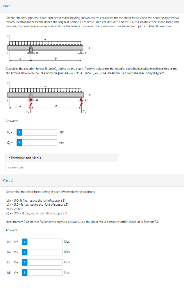
Part 1 For the simply supported beam subjected to the loading shown, derive equations for the shear force V and the bending moment M for any location in the beam. (Place the origin at point A.) Let w=6.0 kips/ft, a=5.0 ft, and b-17.0 ft. Construct the shear-force and bending-moment diagrams on paper and use the results to answer the questions in the subsequent parts of this GO exercise. Calculate the reaction forces B, and C, acting on the beam. Positive values for the reactions are indicated by the directions of the red arrows shown on the free-body diagram below. (Note: Since B, = 0, it has been omitted from the free-body diagram.) A Answers: By= C₂ = i a Save for Later Part 2 B, eTextbook and Media Answers: B B (a) V= (b) V= # (c) V= (d) V= kips Determine the shear force acting at each of the following locations: (a) x = 5.0-ft (i.e., just to the left of support B) (b)x= 5.0+ ft (i.e.. just to the right of support B) (c)x=21.0ft (d) x = 22.0-ft (i.e., just to the left of support C) Note that x = 0 at point A. When entering your answers, use the shear-force sign convention detailed in Section 7.2. kips kips kips kips kips
Part 1 For the simply supported beam subjected to the loading shown, derive equations for the shear force V and the bending moment M for any location in the beam. (Place the origin at point A.) Let w=6.0 kips/ft, a=5.0 ft, and b-17.0 ft. Construct the shear-force and bending-moment diagrams on paper and use the results to answer the questions in the subsequent parts of this GO exercise. Calculate the reaction forces B, and C, acting on the beam. Positive values for the reactions are indicated by the directions of the red arrows shown on the free-body diagram below. (Note: Since B, = 0, it has been omitted from the free-body diagram.) A Answers: By= C₂ = i a Save for Later Part 2 B, eTextbook and Media Answers: B B (a) V= (b) V= # (c) V= (d) V= kips Determine the shear force acting at each of the following locations: (a) x = 5.0-ft (i.e., just to the left of support B) (b)x= 5.0+ ft (i.e.. just to the right of support B) (c)x=21.0ft (d) x = 22.0-ft (i.e., just to the left of support C) Note that x = 0 at point A. When entering your answers, use the shear-force sign convention detailed in Section 7.2. kips kips kips kips kips

International Edition---engineering Mechanics: Statics, 4th Edition
4th Edition
ISBN:9781305501607
Author:Andrew Pytel And Jaan Kiusalaas
Publisher:Andrew Pytel And Jaan Kiusalaas
Chapter6: Beams And Cables
Section: Chapter Questions
Problem 6.42P: For the beam AB shown in Cases 1 and 2, derive and plot expressions for the shear force and bending...

Related questions

Question
Transcribed Image Text:Part 1
For the simply supported beam subjected to the loading shown, derive equations for the shear force V and the bending moment M
for any location in the beam. (Place the origin at point A.) Let w=6.0 kips/ft, a=5.0 ft, and b-17.0 ft. Construct the shear-force and
bending-moment diagrams on paper and use the results to answer the questions in the subsequent parts of this GO exercise.
Calculate the reaction forces B, and C, acting on the beam. Positive values for the reactions are indicated by the directions of the
red arrows shown on the free-body diagram below. (Note: Since B, = 0, it has been omitted from the free-body diagram.)
A
Answers:
By=
C₂ = i
a
Save for Later
Part 2
B,
eTextbook and Media
Answers:
B
B
(a) V=
(b) V=
#
(c) V=
(d) V=
kips
Determine the shear force acting at each of the following locations:
(a) x = 5.0-ft (i.e., just to the left of support B)
(b)x= 5.0+ ft (i.e.. just to the right of support B)
(c)x=21.0ft
(d) x = 22.0-ft (i.e., just to the left of support C)
Note that x = 0 at point A. When entering your answers, use the shear-force sign convention detailed in Section 7.2.
kips
kips
kips
kips
kips
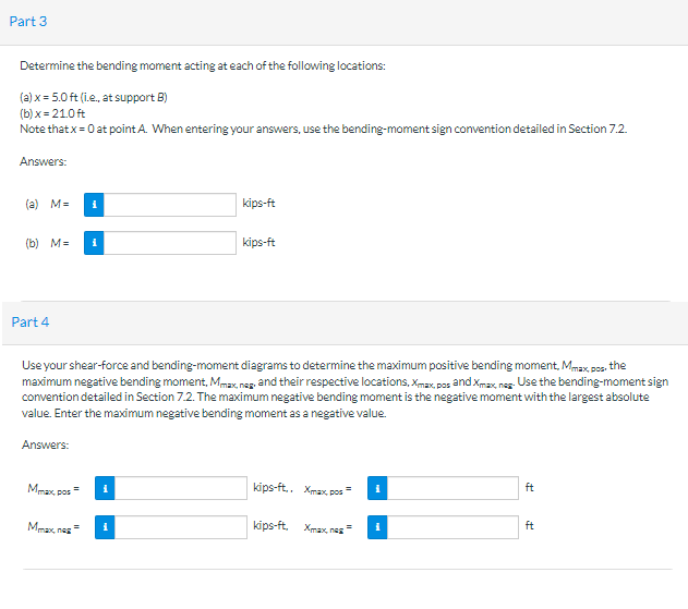
Transcribed Image Text:Part 3
Determine the bending moment acting at each of the following locations:
(a) x = 5.0 ft (i.e., at support B)
(b)x= 21.0 ft
Note that x = 0 at point A. When entering your answers, use the bending-moment sign convention detailed in Section 7.2.
Answers:
(a) M=
(b) M= i
Part 4
Answers:
i
Mmax, pos
Use your shear-force and bending-moment diagrams to determine the maximum positive bending moment, Mmax, pos, the
maximum negative bending moment, Mmax, nag, and their respective locations, Xmax, pas and Xmax, nas. Use the bending-moment sign
convention detailed in Section 7.2. The maximum negative bending moment is the negative moment with the largest absolute
value. Enter the maximum negative bending moment as a negative value.
Maxnes
kips-ft
i
kips-ft
kips-ft.. Xmax, pos
kips-ft. Xmax nag
i
ft
ft
Expert Solution
This question has been solved!
Explore an expertly crafted, step-by-step solution for a thorough understanding of key concepts.

Step by step
Solved in 5 steps with 5 images

Knowledge Booster


Learn more about
Need a deep-dive on the concept behind this application? Look no further. Learn more about this topic, mechanical-engineering and related others by exploring similar questions and additional content below.Recommended textbooks for you
International Edition---engineering Mechanics: St…
Mechanical Engineering
ISBN:
9781305501607
Author:
Andrew Pytel And Jaan Kiusalaas
Publisher:
CENGAGE L

Mechanics of Materials (MindTap Course List)
Mechanical Engineering
ISBN:
9781337093347
Author:
Barry J. Goodno, James M. Gere
Publisher:
Cengage Learning
International Edition---engineering Mechanics: St…
Mechanical Engineering
ISBN:
9781305501607
Author:
Andrew Pytel And Jaan Kiusalaas
Publisher:
CENGAGE L
Mechanics of Materials (MindTap Course List)
Mechanical Engineering
ISBN:
9781337093347
Author:
Barry J. Goodno, James M. Gere
Publisher:
Cengage Learning