1. Design a circuit to realize the following operation on three signals v=A₁v₁ + A₂v₂ + AzV3, with the constraints a) The gains should be in the following ranges as much as possible A₁ = 2.4±0.25, A₂ = -3.6±0.3, A₂ = 1.5±0.2 b) At most two op-amps should be used. c) Use resistors with standard resistance values and tolerance levels of ±5%. The resistances should be in the range 1-100 km2.

Introductory Circuit Analysis (13th Edition)
13th Edition
ISBN:9780133923605
Author:Robert L. Boylestad
Publisher:Robert L. Boylestad
Chapter1: Introduction
Section: Chapter Questions
Problem 1P: Visit your local library (at school or home) and describe the extent to which it provides literature...
icon
Related questions
Question
100%

solve,a,b and c

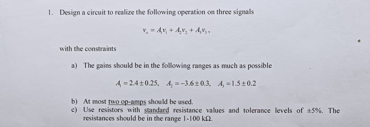
1. Design a circuit to realize the following operation on three signals
v₂ = A₁v₁ + A₂v₂ + AzV3,
with the constraints
a) The gains should be in the following ranges as much as possible
A₁ = 2.4±0.25, A₂=-3.6±0.3, A₂ = 1.5±0.2
b) At most two op-amps should be used.
c) Use resistors with standard resistance values and tolerance levels of ±5%. The
resistances should be in the range 1-100 km2.
Transcribed Image Text:1. Design a circuit to realize the following operation on three signals v₂ = A₁v₁ + A₂v₂ + AzV3, with the constraints a) The gains should be in the following ranges as much as possible A₁ = 2.4±0.25, A₂=-3.6±0.3, A₂ = 1.5±0.2 b) At most two op-amps should be used. c) Use resistors with standard resistance values and tolerance levels of ±5%. The resistances should be in the range 1-100 km2.
Expert Solution
steps

Step by step

Solved in 3 steps with 3 images

Blurred answer
Follow-up Questions
Read through expert solutions to related follow-up questions below.
Follow-up Question

for this circuit do this task 

Simulate the circuit using the simulation software multisim and verify that the circuit performsthe targeted function.Perform tests on your circuit which would verify that the gains remain in the specified rangeswhen the resistances have random errors determined by the tolerance levels (e.g. a 100-Ω resistor with ±5% tolerance may have a resistance value in the range 95-105Ω).

Solution
Bartleby Expert
SEE SOLUTION
Follow-up Question

Make a Report of this experiment

1. I need to give the analysis of this circuit(how i obtain the output voltage from the inputs in terms of resistances) and all calculations that has been made for this design (how the resistances has been chosen to obtain the desired output)

2. Cocnlusion: Make an assesment of the work that has been done. Particularly , discuss whether the design was successful or not. Give reasons if the design failed to satisfy specifications

Solution
Bartleby Expert
SEE SOLUTION
Follow-up Question

can you solve part 1 and 4

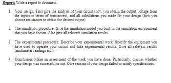
Report: Write a report to document
1. Your design: First give the analysis of your circuit (how you obtain the output voltage from
the inputs in terms of resistances), and all calculations you made for your design (how you
choose resistances to obtain the desired output)
2. The simulation procedure: Give the simulation model you built in the simulation environment
that you have chosen. Also give all relevant simulation results.
3. The experimental procedure: Describe your experimental work. Specify the equipment you
have used to operate your circuit and take experimental results. Give all relevant results
(multimeter readings etc.)
4. Conclusion: Make an assessment of the work you have done. Particularly, discuss whether
your design was successful or not. Give reasons if your design failed to satisfy specifications.
Transcribed Image Text:Report: Write a report to document 1. Your design: First give the analysis of your circuit (how you obtain the output voltage from the inputs in terms of resistances), and all calculations you made for your design (how you choose resistances to obtain the desired output) 2. The simulation procedure: Give the simulation model you built in the simulation environment that you have chosen. Also give all relevant simulation results. 3. The experimental procedure: Describe your experimental work. Specify the equipment you have used to operate your circuit and take experimental results. Give all relevant results (multimeter readings etc.) 4. Conclusion: Make an assessment of the work you have done. Particularly, discuss whether your design was successful or not. Give reasons if your design failed to satisfy specifications.
Solution
Bartleby Expert
SEE SOLUTION
Knowledge Booster
Operational amplifier
Learn more about
Need a deep-dive on the concept behind this application? Look no further. Learn more about this topic, electrical-engineering and related others by exploring similar questions and additional content below.
Similar questions
  • SEE MORE QUESTIONS
Recommended textbooks for you
Introductory Circuit Analysis (13th Edition)
Electrical Engineering
ISBN:
9780133923605
Author:
Robert L. Boylestad
Publisher:
PEARSON
Delmar's Standard Textbook Of Electricity
Electrical Engineering
ISBN:
9781337900348
Author:
Stephen L. Herman
Publisher:
Cengage Learning
Programmable Logic Controllers
Electrical Engineering
ISBN:
9780073373843
Author:
Frank D. Petruzella
Publisher:
McGraw-Hill Education
Fundamentals of Electric Circuits
Electrical Engineering
ISBN:
9780078028229
Author:
Charles K Alexander, Matthew Sadiku
Publisher:
McGraw-Hill Education
Electric Circuits. (11th Edition)
Electrical Engineering
ISBN:
9780134746968
Author:
James W. Nilsson, Susan Riedel
Publisher:
PEARSON
Engineering Electromagnetics
Electrical Engineering
ISBN:
9780078028151
Author:
Hayt, William H. (william Hart), Jr, BUCK, John A.
Publisher:
Mcgraw-hill Education,