4. Note the readings of voltmeter, ammeter and wattmeter by carefully and fill them in table 1 Table 1: The measured parameters during open circuit test of the induction motor Parameter VLL Measurement Value IL P1 P2 Pinput 5. Take the readings quickly so that the machine does not heat up due to full load copper lossestaking place at this condition. 6. Reduce the voltage to zero and turn the main switch off. Discussion: 1. Draw the circuit diagram of short circuit test using PSIM. Give some explanations 2. What is the value of the slip? 3. What happened to rotor's resistance? 4. Is the input voltage small or rated during short circuit test? Why? 5. Calculate the RX,X 2 6. When r2/s is split into a series connection of r2' and r2' {(1/s)-1} in the rotor equivalent circuit ofan induction machine, what do the power absorbed by the individual resistors physically represent? 7. How does the equivalent circuit of an induction motor simplify to under blocked rotor conditions? Justify. For this test, the motor shaft is blocked by your hand so that it cannot turn. The motor terminals are connected to a 3-phase supply. The rotor becomes the secondary of a transformer operating at the supply frequency. So, the blocked rotor test is similar to the short circuit test on a transformer. It is performed to calculate the series parameters of the induction machine i.e., its leakage impedances. The rotor is blocked to prevent rotation and balanced voltages are applied to the stator terminals where the rated current is achieved. Under the reduced voltage condition and rated current, core loss and magnetizing component ofthe current are quite small percent of the total current, equivalent circuit reduces to the form shown in Fig.(1). R1 jX1 m Isc +W Vph R2' jX2' Fig. 1: Equivalent circuit for blocked rotor test The slip for the blocked rotor test is unity since the rotor is stationary. The resulting speed-dependent equivalent resistance r2' {(1/s)-1} goes to zero and the resistance of the rotor branch of the equivalent circuitbecomes very small. Thus, the rotor current is much larger than current in the excitation branch of the circuitsuch that the excitation branch can be neglected. Voltage and power are measured at the motor input. Experimental Procedure: 1. Connect the circuit as shown in the connection diagram in Figure 2. U 11 A V No W 12 A 5 U₁ IM VLL1 T V Shaft VLL2 W Heavy Mechanical Load Fig.2. Short circuit test of induction motor
4. Note the readings of voltmeter, ammeter and wattmeter by carefully and fill them in table 1 Table 1: The measured parameters during open circuit test of the induction motor Parameter VLL Measurement Value IL P1 P2 Pinput 5. Take the readings quickly so that the machine does not heat up due to full load copper lossestaking place at this condition. 6. Reduce the voltage to zero and turn the main switch off. Discussion: 1. Draw the circuit diagram of short circuit test using PSIM. Give some explanations 2. What is the value of the slip? 3. What happened to rotor's resistance? 4. Is the input voltage small or rated during short circuit test? Why? 5. Calculate the RX,X 2 6. When r2/s is split into a series connection of r2' and r2' {(1/s)-1} in the rotor equivalent circuit ofan induction machine, what do the power absorbed by the individual resistors physically represent? 7. How does the equivalent circuit of an induction motor simplify to under blocked rotor conditions? Justify. For this test, the motor shaft is blocked by your hand so that it cannot turn. The motor terminals are connected to a 3-phase supply. The rotor becomes the secondary of a transformer operating at the supply frequency. So, the blocked rotor test is similar to the short circuit test on a transformer. It is performed to calculate the series parameters of the induction machine i.e., its leakage impedances. The rotor is blocked to prevent rotation and balanced voltages are applied to the stator terminals where the rated current is achieved. Under the reduced voltage condition and rated current, core loss and magnetizing component ofthe current are quite small percent of the total current, equivalent circuit reduces to the form shown in Fig.(1). R1 jX1 m Isc +W Vph R2' jX2' Fig. 1: Equivalent circuit for blocked rotor test The slip for the blocked rotor test is unity since the rotor is stationary. The resulting speed-dependent equivalent resistance r2' {(1/s)-1} goes to zero and the resistance of the rotor branch of the equivalent circuitbecomes very small. Thus, the rotor current is much larger than current in the excitation branch of the circuitsuch that the excitation branch can be neglected. Voltage and power are measured at the motor input. Experimental Procedure: 1. Connect the circuit as shown in the connection diagram in Figure 2. U 11 A V No W 12 A 5 U₁ IM VLL1 T V Shaft VLL2 W Heavy Mechanical Load Fig.2. Short circuit test of induction motor

Power System Analysis and Design (MindTap Course List)
6th Edition
ISBN:9781305632134
Author:J. Duncan Glover, Thomas Overbye, Mulukutla S. Sarma
Publisher:J. Duncan Glover, Thomas Overbye, Mulukutla S. Sarma
Chapter3: Power Transformers
Section: Chapter Questions
Problem 3.34MCQ: Consider Figure 3.25 of the text for a transformer with off-nominal turns ratio. (i) The per-unit...

Related questions
Question
Vll=164v IL=0.48A P1=75W P2=75W Pinput=150w please solve question 5 in discussion section
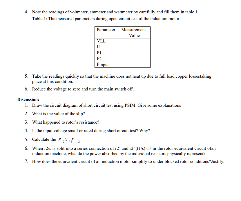
Transcribed Image Text:4. Note the readings of voltmeter, ammeter and wattmeter by carefully and fill them in table 1
Table 1: The measured parameters during open circuit test of the induction motor
Parameter
VLL
Measurement
Value
IL
P1
P2
Pinput
5. Take the readings quickly so that the machine does not heat up due to full load copper lossestaking
place at this condition.
6. Reduce the voltage to zero and turn the main switch off.
Discussion:
1. Draw the circuit diagram of short circuit test using PSIM. Give some explanations
2. What is the value of the slip?
3. What happened to rotor's resistance?
4. Is the input voltage small or rated during short circuit test? Why?
5. Calculate the RX,X 2
6. When r2/s is split into a series connection of r2' and r2' {(1/s)-1} in the rotor equivalent circuit ofan
induction machine, what do the power absorbed by the individual resistors physically represent?
7. How does the equivalent circuit of an induction motor simplify to under blocked rotor conditions? Justify.
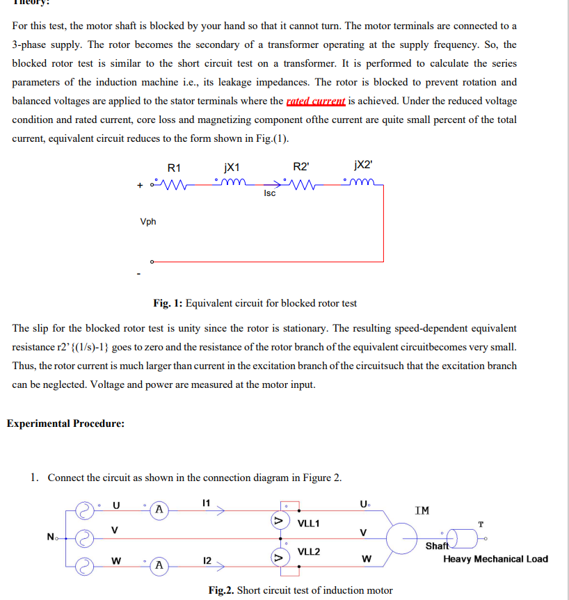
Transcribed Image Text:For this test, the motor shaft is blocked by your hand so that it cannot turn. The motor terminals are connected to a
3-phase supply. The rotor becomes the secondary of a transformer operating at the supply frequency. So, the
blocked rotor test is similar to the short circuit test on a transformer. It is performed to calculate the series
parameters of the induction machine i.e., its leakage impedances. The rotor is blocked to prevent rotation and
balanced voltages are applied to the stator terminals where the rated current is achieved. Under the reduced voltage
condition and rated current, core loss and magnetizing component ofthe current are quite small percent of the total
current, equivalent circuit reduces to the form shown in Fig.(1).
R1
jX1
m
Isc
+W
Vph
R2'
jX2'
Fig. 1: Equivalent circuit for blocked rotor test
The slip for the blocked rotor test is unity since the rotor is stationary. The resulting speed-dependent equivalent
resistance r2' {(1/s)-1} goes to zero and the resistance of the rotor branch of the equivalent circuitbecomes very small.
Thus, the rotor current is much larger than current in the excitation branch of the circuitsuch that the excitation branch
can be neglected. Voltage and power are measured at the motor input.
Experimental Procedure:
1. Connect the circuit as shown in the connection diagram in Figure 2.
U
11
A
V
No
W
12
A
5
U₁
IM
VLL1
T
V
Shaft
VLL2
W
Heavy Mechanical Load
Fig.2. Short circuit test of induction motor
Expert Solution
This question has been solved!
Explore an expertly crafted, step-by-step solution for a thorough understanding of key concepts.

Step by step
Solved in 2 steps with 3 images

Recommended textbooks for you
Power System Analysis and Design (MindTap Course …
Electrical Engineering
ISBN:
9781305632134
Author:
J. Duncan Glover, Thomas Overbye, Mulukutla S. Sarma
Publisher:
Cengage Learning
Power System Analysis and Design (MindTap Course …
Electrical Engineering
ISBN:
9781305632134
Author:
J. Duncan Glover, Thomas Overbye, Mulukutla S. Sarma
Publisher:
Cengage Learning