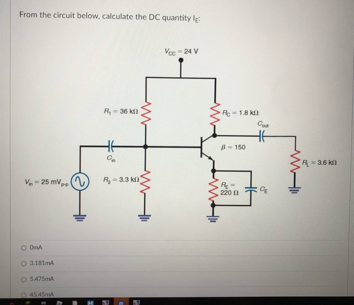
From the circuit below, calculate the DC quantity lĘ:


Q: 1- Describe how an oscilloscope can be used to measure the voltage and duration of an unknown signal…
A: Since you have asked multiple question, we will solve the first question for you. If youwant any…
Q: An SSB transmitter radiates 100 W in a 75 ohms load. The carrier signal is modulated by two tones,…
A: Given information: The SSB transmitter radiates 100 W of power in a load of resistance 75 ohms. The…
Q: 1. When are the p-n junctions of the n-channel FET blocked? 2. When cre the p-n junctions of the…
A: Since you have posted the questions with multiple subpart so we are supposed to answer 3 subpart.
Q: nd the maximum power de sume that the antennas are polarization transmitting antenna is the…
A:
Q: Obtain the equivalent impedance of the circuit. j4 2 ell 2Ω Zea j2 2 -/2 2 ll ww
A: This question belongs to circuit theory . It is based on the concept of delta star conversion for…
Q: A11 kV,15 km length primary feeder connected to a balanced load of 950 kW at a power factor of 0.85…
A: We assumed three phase feeder as nothingI is mentioned about single phase or three phase. given…
Q: O2: The coaxial cable in Fig. below has an inner conductor radius of 0.5 mm and an outer conductor…
A: This question belongs to power system . It is based on the concept of coaxial cable . It is about…
Q: For RF line of sight or LOS communication, ____ of the first Fresnel zone must be clear of…
A: Note: We are authorized to answer the first question since the exact one wasn’t specified. Please…
Q: power of 25 at its input and 8 at its
A:
Q: Question 1 State Gauss's law. Deduce Coulomb's law from Gauss's law, thereby affirming that Gauss's…
A:
Q: Find the Norton equivalent at terminals a-b of the circuit. * 10 2 a 202 4 A 10 Ω3
A:
Q: The power density of a plane wave propagating in free space is 100 µW/m?. Determine (a) the electric…
A: Power Density: The quantity of power (time rate of energy transfer) per unit volume is known as…
Q: Solve for power and complex power for every component
A: In this question, We need to determine the complex power for every component? We know complex…
Q: The circuit shown is at steady state before the switch closes. The inductor currents are both zero…
A: Given
Q: For the circuit find dve(0*)/dt, di (0*)/dt, i16y(0+), vc(∞) and i (∞). Assume that the switch was…
A:
Q: Determine the conductance of a resistor having a resistance of 5 ohms.
A: The conductance is the inverse of resistance and the unit of conductance is siemens.
Q: a. Given the Bode diagram in figure 2, obtain the following by showing horizontal and vertical line…
A: The required parameter can be analyzed by using the bode magnitude and phase plot.
Q: Fill in the blank : For the circuit shown below, solve for Av VoD = 20 V Ipss = 10 mA Ro = 4.7 k2…
A:
Q: In a boost converter, when the MOSFET is off, the inductor is: O discharging charginng idle…
A: In a boost converter, when the mosfet is off, the inductor is, Select correct answer
Q: What is the bandwidth of a narrowband FM signal generated by a 2 kHz audio signal and 110 MHz FM…
A:
Q: V(t) b f(t) m
A: The solution is given below
Q: 1. Determine the frequency of oscillation of a three-stage ladder network oscillator in which C= 30…
A:
Q: If BL=BA and AL=34 hex are multiplied using MUL BL, where do the results appear?
A:
Q: Fill in the blank : Calculate the value of Ro that will provide an I Dfon) of 10 mA for V DD - 15V:…
A:
Q: 18-18 You are part of a design team that is planning the instal- lation of a network for an…
A: 5 Twisted pair cable 5 Twisted-pair cable means , The cabling of 4 wires especially for Computer…
Q: An electric field intensity Ez =1kV/m at point P(-2,1,-1) in free space is caused by a charge Qo…
A:
Q: Consider two signals xi(t) and x2(t); signal x1(t) is sampled at -4 and 8 and signal x2 is sampled…
A: The bandwidth of a signal can be explained as the rate at which the maximum frequency signal can be…
Q: says to determine V in the circuit (and use Wye-Delta or Delta-Wye) Thanks!
A:
Q: neal power output of the 185 W, 110 V, 60 Hz, single-phase induction motor whose constants referred…
A:
Q: if (+jS x+jy, the find the value of xtjy. 2-)
A:
Q: FM signal which is being broadcast in 88 MHz – 108 MHz
A: Amplifier An electronic device or we can say circuit arrangement in which for small amplitude signal…
Q: Using Carson's rule. What is the bandwidth (kHz) of an FM signal with 5 kHz maximum frequency…
A:
Q: 3. Derive the ABCD constants for a line having resistance of 0.1 2/mi, reactance 0.86 2/mi, and…
A: Given R= 0.1 Ω /mi XL= 0.86 Ω /mi Xc= 0.04 Ω /mi
Q: Explain the operation of the DM modulator used in module ED-2960G. Discuss the advantages and…
A:
Q: 1. A 240 V, 50 Hz, single-phasc capacitor start a.c. motor is loaded such that the slip is 6 %. The…
A:
Q: In a boost converter, when the MOSFET is off, the inductor is: O discharging charginng O idle…
A:
Q: A power transmission line conducts current from a 6000V generator to three loads A,B,C, the loads…
A:
Q: 3. Analyze the following design based on different values of X and Y and determine whether it can…
A:
Q: 1) Draw the equation/picture for the following chart:
A: Since you have asked multiple questions, we will solve the first question for you. If you want any…
Q: receiver connected to an antenna whose resistance is 50Ω has an equivalent noise resistance of 30Ω.…
A: We need to find noise figure .
Q: 21. An AM signal has a carrier frequency of 3MHZ and an amplitude of 5V peak. It is modulated by a…
A:
Q: EX A.2 Sketch the transfer curve for a p - channel device with Ipss = 6 mA and Vp = 3 V.
A: Given, P-channel device having IDSS =6 mA VP = 3 V
Q: acitance of 10 = 1 mm, b
A:
Q: Steady-state has been establish at t = 0-. Determine the discharge rates of the capacitor dvC(0+)/dt…
A:
Q: EXAMPLE 12.12 For the circuit of Fig. 12.19, determine the maximum power dissipated by the output…
A: The given circuit is a class B power amplifier circuit. The power dissipated by the output…
Q: Two Alternators working in parallel supply a lighting bulb of 3MW together with induction motor load…
A: In this question, Two alternator are connected in the parallel and supplied to the power two…
Q: How does a synchronous machine differ from an induction machine, in construction, in P U and O flow,…
A: Synchronous machines differ from Induction machines in many aspects. The fundamental difference…
Q: Find The fourier transform of the function: flany) = S(xcosD +ysin@-8) t
A:
Q: A phase modulator has kp=1.5 rad/V. What rms voltage of a sine wave would cause a peak phase…
A:

Step by step
Solved in 2 steps


- According to the circuit given in the figure, VT=25mV, |VBE|=0.7V, R1=1487.51Kohm, R2= 7.42Kohm, R3= 6.71Kohm , R4= 2.87Kohm, VCC= 13.00V, VEE= 1.00V , VA=28.21V , Beta= 120.00 , Rs= 36.18ohm, Ry= 15.61Kohm Calculate the IC current, Ri, R0 and voltage gain(V0/V1) according to the source by performing a complete analysis. When performing your operations, 2 steps will be taken after the point. choose the closest one from the stylish ones according to the +/-10% margin of error. There is only 1 correct answer to the question.In the circuit given in the figure, VT = 25mV, | VBE | = 0.7V, R1 = 1402.66Kohm, R2 = 32.67Kohm, R3 = 2.91Kohm, R4 = 1.25Kohm, VCC = 10.00V, VEE = -5.00V, VA = 25.00V, Since Beta = 208.00, Rs = 28.63ohm, Ry = 13.62Kohm, calculate the IC current, Ri, R0 and the voltage gain according to the Source (V0 / V1) by full analysis.In the circuit given in the figure, VT = 25mV, | VBE | = 0.7V, R1 = 1519.62Kohm, R2 = 48.01Kohm, R3 = 3.22Kohm, R4 = 1.38Kohm, VCC = 13.00V, VEE = -6.00V, VA = 19.82V, Since Beta = 163.00, Rs = 23.65 ohm, Ry = 18.08Kohm, by Source calculate IC current, Ri, R0 and voltage gain (V0 / V1) with full analysis.
- In the circuit given in the figure VT = 25mV, | VBE | = 0.7V, R1 = 712.91Kohm, R2 = 43.27Kohm, R3 = 2.29Kohm, R4 = 0.98Kohm, VCC = 10.00V, VEE = -4.00V, VA = 10.06V, Beta = 137.00, Rs = 38.43ohm, Ry Calculate the IC current according to = 16.55Kohm, Ri, R0 and the voltage gain (V0 / V1) according to the Source by full analysis When making your transactions, 2 steps will be taken after the point. Select the closest option according to +/- 10% margin of error. There is only one correct answer to the question.describe the working principle OF MOS (need only handwritten solution .otherwise downvote.)In the Boost DA-DA circuit:Source voltage (E) value: in the range of [17-29] (volts),Switching frequency (f) value: 20 khz,Voltage between load ends: 40VCapacitance value: 470uFPower dissipated at load: 10 watts What is the lowest inductance L, in uH, that can keep the DC-DC converter in continuous current under these conditions? a) 269.3731 b) 415.4375 c) 364.8204 d) 163.6472 e) 578.1875
- Consider the circuit of Figure 1 using VCC = 10 volts, R1 = 10 kΩ, R2 = 3.3 kΩ, Re = 4.7 kΩ and Rc = 5.6 kΩ. Using the approximation of a lightly loaded “stiff” voltage divider, determine the ideal endpoints of the DC load line and the Q point, and record these in Table 1.1. Can you show process of solutionDefine three clockwise mesh current from the circuit and employ the supermesh technique to obtain a numerical value for each??a- In the circuit shown in Figure VCC = 13.6 V, görülen = 145and since the transistor is of silicon type,Required for IC = 5 mA when VCE = 6.8 VCalculate the RC and RB values. Calculate the power consumed by the transistor.b- RE = 1.2K to the emitter end of the transistorIf connected, calculate VCE, IC, IB currents.Interpret the final state of the circuit.
- Q3:Choose One of the following: : (A)In common emmiter voltage divider bias of BJT, Vcc = 25V; R1= 10 k ohm; R2, = 2.2 k ohm ;Rc = 3.6 k ohm and RE = 1 k ohm.Determain Vec at ß = 120.using Exact analysis Draw the equvelent circuit inaddition the DC load line curve . (B)For self bais(Emitter resistace bais) of BJT,Vcc= 22 V, lb = 45macroA, a = 0.99, RE = 1 k ohm. Determain VCe Draw the equvelent circuit inaddition to DC load line curve.For the circuit given below, let VBEQ=0.7 V, then the Q-point(VCEQ,ICEQ) equals:For the circuit in the figure, find the ones requested in the questions by using the following values? Vcc= 11 V, β=125, RF=227 kΩ, RC=3,6 kΩ, RE=0,9 kΩ IB=? IC=? IE=? VCE=? VCB=?