From the circuit in Figure 3, the voltage across the ideal diode is 1.5 kQ 10 V O 2.5 ko Figure 3 O V 0.7 V 5 V 10 V
From the circuit in Figure 3, the voltage across the ideal diode is 1.5 kQ 10 V O 2.5 ko Figure 3 O V 0.7 V 5 V 10 V

Electricity for Refrigeration, Heating, and Air Conditioning (MindTap Course List)
10th Edition
ISBN:9781337399128
Author:Russell E. Smith
Publisher:Russell E. Smith
Chapter12: Electronic Control Devices
Section: Chapter Questions
Problem 3RQ: Diodes and rectifiers allow current to _________.
flow in one direction only
flow in both...

Related questions
Question
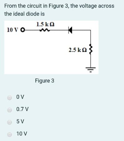
Transcribed Image Text:From the circuit in Figure 3, the voltage across
the ideal diode is
1.5 kO
10 V O
2.5 ka
Figure 3
O V
0.7 V
5 V
10 V
Expert Solution
This question has been solved!
Explore an expertly crafted, step-by-step solution for a thorough understanding of key concepts.

Step by step
Solved in 2 steps with 1 images

Knowledge Booster


Learn more about
Need a deep-dive on the concept behind this application? Look no further. Learn more about this topic, electrical-engineering and related others by exploring similar questions and additional content below.Recommended textbooks for you
Electricity for Refrigeration, Heating, and Air C…
Mechanical Engineering
ISBN:
9781337399128
Author:
Russell E. Smith
Publisher:
Cengage Learning


Delmar's Standard Textbook Of Electricity
Electrical Engineering
ISBN:
9781337900348
Author:
Stephen L. Herman
Publisher:
Cengage Learning
Electricity for Refrigeration, Heating, and Air C…
Mechanical Engineering
ISBN:
9781337399128
Author:
Russell E. Smith
Publisher:
Cengage Learning
Delmar's Standard Textbook Of Electricity
Electrical Engineering
ISBN:
9781337900348
Author:
Stephen L. Herman
Publisher:
Cengage Learning