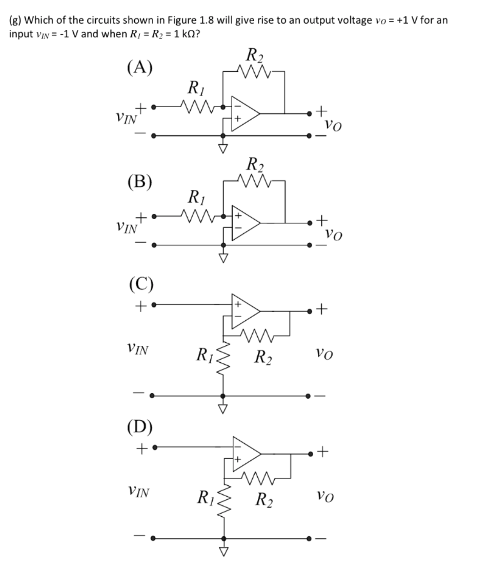
(g) Which of the circuits shown in Figure 1.8 will give rise to an output voltage vo = +1 V for an input vIN = -1 V and when R1 = R2 = 1 kN? R2 (A) R1 VIN vo R2 (В) R1 VIN Vo (C) + VIN R2 vo (D) VIN R1 R2 vo +


Quantization and Resolution
Quantization is a methodology of carrying out signal modulation by the process of mapping input values from an infinitely long set of continuous values to a smaller set of finite values. Quantization forms the basic algorithm for lossy compression algorithms and represents a given analog signal into digital signals. In other words, these algorithms form the base of an analog-to-digital converter. Devices that process the algorithm of quantization are known as a quantizer. These devices aid in rounding off (approximation) the errors of an input function called the quantized value.
Probability of Error
This topic is widely taught in many undergraduate and postgraduate degree courses of:

Step by step
Solved in 2 steps


