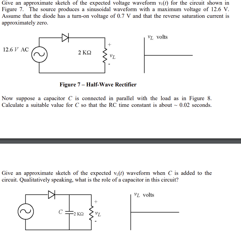
Give an approximate sketch of the expected voltage waveform vi(t) for the circuit shown in Figure 7. The source produces a sinusoidal waveform with a maximum voltage of 12.6 V. Assume that the diode has a turn-on voltage of 0.7 V and that the reverse saturation current is approximately zero. D 12.6 V AC 2 ΚΩ VL VL volts Figure 7- Half-Wave Rectifier Now suppose a capacitor C is connected in parallel with the load as in Figure 8. Calculate a suitable value for C so that the RC time constant is about ~ 0.02 seconds.
Give an approximate sketch of the expected voltage waveform vi(t) for the circuit shown in Figure 7. The source produces a sinusoidal waveform with a maximum voltage of 12.6 V. Assume that the diode has a turn-on voltage of 0.7 V and that the reverse saturation current is approximately zero. D 12.6 V AC 2 ΚΩ VL VL volts Figure 7- Half-Wave Rectifier Now suppose a capacitor C is connected in parallel with the load as in Figure 8. Calculate a suitable value for C so that the RC time constant is about ~ 0.02 seconds.

Introductory Circuit Analysis (13th Edition)
13th Edition
ISBN:9780133923605
Author:Robert L. Boylestad
Publisher:Robert L. Boylestad
Chapter1: Introduction
Section: Chapter Questions
Problem 1P: Visit your local library (at school or home) and describe the extent to which it provides literature...

Related questions

Question
Transcribed Image Text:Give an approximate sketch of the expected voltage waveform vi(t) for the circuit shown in
Figure 7. The source produces a sinusoidal waveform with a maximum voltage of 12.6 V.
Assume that the diode has a turn-on voltage of 0.7 V and that the reverse saturation current is
approximately zero.
12.6 V AC
2 ΚΩ
C
Figure 7- Half-Wave Rectifier
Now suppose a capacitor C is connected in parallel with the load as in Figure 8.
Calculate a suitable value for C so that the RC time constant is about ~ 0.02 seconds.
-2 ΚΩ
+
Give an approximate sketch of the expected v₁(t) waveform when C is added to the
circuit. Qualitatively speaking, what is the role of a capacitor in this circuit?
+
VL
VL
VL volts
VL volts
Expert Solution
This question has been solved!
Explore an expertly crafted, step-by-step solution for a thorough understanding of key concepts.

This is a popular solution!

Trending now
This is a popular solution!

Step by step
Solved in 4 steps with 6 images

Knowledge Booster


Learn more about
Need a deep-dive on the concept behind this application? Look no further. Learn more about this topic, electrical-engineering and related others by exploring similar questions and additional content below.Recommended textbooks for you
Introductory Circuit Analysis (13th Edition)
Electrical Engineering
ISBN:
9780133923605
Author:
Robert L. Boylestad
Publisher:
PEARSON

Delmar's Standard Textbook Of Electricity
Electrical Engineering
ISBN:
9781337900348
Author:
Stephen L. Herman
Publisher:
Cengage Learning

Programmable Logic Controllers
Electrical Engineering
ISBN:
9780073373843
Author:
Frank D. Petruzella
Publisher:
McGraw-Hill Education
Introductory Circuit Analysis (13th Edition)
Electrical Engineering
ISBN:
9780133923605
Author:
Robert L. Boylestad
Publisher:
PEARSON
Delmar's Standard Textbook Of Electricity
Electrical Engineering
ISBN:
9781337900348
Author:
Stephen L. Herman
Publisher:
Cengage Learning
Programmable Logic Controllers
Electrical Engineering
ISBN:
9780073373843
Author:
Frank D. Petruzella
Publisher:
McGraw-Hill Education

Fundamentals of Electric Circuits
Electrical Engineering
ISBN:
9780078028229
Author:
Charles K Alexander, Matthew Sadiku
Publisher:
McGraw-Hill Education

Electric Circuits. (11th Edition)
Electrical Engineering
ISBN:
9780134746968
Author:
James W. Nilsson, Susan Riedel
Publisher:
PEARSON

Engineering Electromagnetics
Electrical Engineering
ISBN:
9780078028151
Author:
Hayt, William H. (william Hart), Jr, BUCK, John A.
Publisher:
Mcgraw-hill Education,