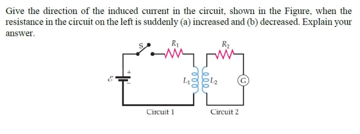
Give the direction of the induced current in the circuit, shown in the Figure, when the resistance in the circuit on the left is suddenly (a) increased and (b) decreased. Explain your answer. R1 R2
Q: Consider a circuit shown in the right figure where we have a battery of emf E, a capacitor of…
A:
Q: Apply or Use Kirchhoff’s Laws in solving currents in a circuit. How many nodes and loops are there?…
A:
Q: Q2: For the circuit find the power absorbed by 20 resistance by using Kirchhoff's laws.
A:
Q: Solve the output FIND CURRENT FLOWING THROUGH Z1 FIND CURRENT FLOWING THROUGH Z2
A: The given circuit is as shown below with mesh currents and assumed current directions in each…
Q: Consider a circuit shown in the right figure where we have a battery of emf E, a capacitor of…
A: Capacitor will work as open circuit at final stage and work as short circuit at initial stage .
Q: Consider the circuit shown in the figure below. Given that R₂/R₁ = 2 and R3/R₁ = 6, the current…
A: In this question we need to choose a correct option.
Q: Figure Q1b shows the voltage and current waveforms from an AC circuit. A student states that these…
A: Different types of AC circuit shown below. Fig.-1 It represents a Pure resistive circuit. In pure…
Q: By measuring the currents and times and then draw the current vs time graph using the measurement at…
A: The storage elements such as inductors and capacitors have the property to store energy across them.…
Q: A battery can be modeled by a voltage source Vt in series with a resistance Rt. Assuming that the…
A: Drawing series circuit diagram of voltage Vt with resistances RL and Rt. Maximum power theorem…
Q: Consider the circuit shown in the figure below. Given that R2/R1 = 2, the current passing through…
A: In this question we need to find a time constant of the given circuit
Q: Using the circuit below: a. Redraw the circuit where Ry = 4k2 b. Find Is (current from the DC…
A: Ry = 4 k ohm
Q: Assuming all resistance are in Q2/ write the nodal equation for the circuit shown below.
A: Circuit diagram is given as, Node 2 is directly connected to 8 V voltage source. Therefore, V2=8 V
Q: Q5/ Using Kirchhoff Laws for the circuit below determine the value and the direction of the current…
A: The given circuit is shown below:
Q: P4.38. For the circuit shown in Figure P4.38, find an expression for the current i(t) and sketch it…
A: we need to find iL(t),vL(t) and plot the curve for each
Q: The figure shows a circuit containing an electromotive force, a capacitor with a capa where Q is the…
A: When no current flows, the electromotive force (EMF) equals the difference in terminal potential.…
Q: In the figure below, N batteries, each with electromotive force ɛ and internal resistance r, are…
A: According to question: The circuit is drawn as
Q: For the given circuit, find the currents and (a) right after switch S is closed and (b) a long time…
A: " Since you have posted a question with multiple subparts, we will solve the first three subparts…
Q: Find the equation for current through X2. Provide
A:
Q: From the circuit shown in the figure,
A:
Q: Ohm's law gives the relationship between voltage, resistance, and current in a simple circuit: V =…
A: We know that the relationship between voltage, resistance, and current is given by Ohm's law in a…
Q: The switch of Figure I has been closed for a long time and opened at t- 0 sec. (i) Find the…
A:
Q: If the potential of point P in the circuit given in the figure is 100V What is the potential of the…
A: Consider the given circuit,
Q: For circuit shown, find the equivalent resistance seen by the source and the power developed by the…
A: First calculate equivalent resistance by combining the resistors in series and parallel. Power…
Q: A cylindrical solenoid 49 cm long with a radius of 7 mm has 325 tightly-wound turns of wire…
A: Given:l=49cmr=7mmN=325a=3cmb=2cmR=135ΩN2=2
Q: Q4. The series RL circuit of Figure Q4 is subject to a unit step voltage input of height 5 volts at…
A:
Q: In the circuit shown in Figure below, the voltage source is supplying 29.65 V. The switch remains…
A:
Q: It is required that a loading of 3 kW be maintained in a heating element at an initial temperature…
A:
Q: In the circuit in the figure, a potential difference V is applied as shown. Determine the value of…
A:
Q: Consider a series of slabs as shown below, where RT is the thermal resistance through slab i and T…
A: When thermal resistances are in series then the equivalent is RTs=RT1+RT2. When thermal resistance…
Q: For the networks shown in Figures (Q1), the switch has been at position "A" for a long time. At t2o,…
A: Consider the circuit at position A, the switch is at position A for longer time hence capacitor is…
Q: A voltage source, V, supplying 100 V, is connected to two resistors R1, with a resistance of 4002,…
A: Part (A):- The given question describes that the voltage source of 100 V is connected with two…
Q: For the circuit shown in the figure, obtain the current in resistor R if its resistance is 20Ω.…
A:
Q: write the final equation of point V2 * V4 ЗА V1 22 V2 U8 V3 4Ω 2. 2 A
A: Nodal analysis uses Kirchhoff's current law and ohm's law. The equation is derived below.
Q: For the circuit below, solve for the following: a. RT b. IT (pk), IT (p-p), IT (rms), IT (avg) c.…
A: Hello. Since your question has multiple sub-parts, we will solve the first three sub-parts for you.…
Q: Solve VR1 VR2 VR3 VR4 VR5 VR6 and all the currents on this given circuit
A:
Q: A nonideal voltage source is modeled in FigureP3.72 as an ideal source in series with a resistance…
A: The connected voltage source is ideal. The biasing through the resistors can be used for modeling…
Q: solve the circuit shown in Figure by Mesh current equation
A: Apply KVL to both loops with clockwise direction as figure(b) Loop 1: 35-3I1-2I3=0…
Q: Apply Kirchhoff’s Laws in solving currents in a circuit. How many nodes and loops are there?
A:
Q: Using Kirchoff's Law determine the following current R1=12 R2=60 R3=92 V1=20volts V2=5 volts R R, V1…
A:
Q: Q1- For the circuit shown in Figure, if the colors of R1 are (Brown, Black, Red, Gold) and the…
A: When two resistors R1 and R2, are connected in series, the same current flows through them. The…
Q: (c) Find the resistor RL value that can provide maximum power transfer from the circuit shown in…
A:
Q: Determine step by step the simple form of the block diagram given in Figure Q2(a).
A: Given: The block diagram of the system is: To find: Determine step by step the simple form of the…
Q: Given that the resistor in the figure is made of material its resistivity is p with radiuses r,, r2…
A:
Q: Using Kirchoff's Law determine the following current R1=10 R2=80 R3=50 V1=24volts V2=D10 volts R1 R3…
A: Let current in loop 1 be i1 and loop 2 be i2. (note :- Replace R2 and R3 in figure as it is named…
Q: An electric toothbrush has a base designed to hold the toothbrush handle when not in use. As shown,…
A: Given data, Current =I Number of turns in the handle = NH Number of turns in the solenoid= NB…
Q: Q1: Given the circuit shown in figure below, determine the mesh currents in the circuit.
A:
Q: Consider a circuit shown in the right figure where we have a battery of emf E, a capacitor of…
A: Given circuit shown with DC source
Q: A 9ohm resistor is connected to a solenoid and a power source of 10V. The solenoid has a radius of…
A: Given V = 10V R = 9 ohm r =15 cm N =200 l = 2cm
Solve it correctly please.
Trending now
This is a popular solution!
Step by step
Solved in 3 steps with 3 images
- Compute for IN, RN and the current passing though the 25-ohm resistor using Norton’s Theorem. Answer neatly and please explaiin the processcan you please elaborate on how you got the equations? if its nodal analysis can you explain it in detail? also E0=v2 as well? why is v0=e0 but v2 isnt? please answer my concerns.For the mutual electric circuit shown in figure beside, find the set values of mesh currents I1 & I2?
- determine the currents i1, i2, and i3 using Gauss-Jordan Elimination What is the voltage across the 3 ohm resistance? What is the power across the 3 ohm resistance?AnalyzethecircuitinFigureQ2(b)for:(i)Impedanceseenbythesource. (ii)CurrentI1andI2. (iii)Energystoredinmagneticcouplewhenangularfrequency,?=2rad/s,andtime,t=2s.A)I2(t) Find the mathematical expression for B)Find the complex power on inductance=?
- A 30-volt electromotive force is applied to an ??-series circuit in which the inductance is 0.1 henry and the resistance is 50 ohms. Find the current ?(?) if ?(0) = 0. Determine the current as ? → ∞.Write the differential equation for t > 0 for iC in the given figure. Assume VS = 9 V, RS = 4 kohm, R1 = 11 kohm, and R2 = R3 = 20 kohm.Answer the following points in detail and rigorously. Instead of resorting to formulas, develop from basic principles (laws of voltages and currents, definition of electrical power, properties of phasors, among others). a) Show that the complex power consumed by two elements in parallel is the sum of the individual complex powers. Then repeat the procedure but for two elements in series. b What meaning would you give to the P consumed by an element? Which to Q? c) Suppose you know P and Q for a two-terminal element. What is the power factor of this element? When would you be ahead and when would you be behind? d) Suppose you know the equivalent resistance R and the equivalent reactance X of a two-terminal passive network. What is the power factor of this network? When would you be ahead and when would you be behind?
- Please explain this equation for nodal analysis. Why did Vs1 and Vs2 became negative? Why did Vs3 became positive? The flow of current I1, I2, and I3 is already given. I just need an explanation why it became positive or negative on the equation.For the number 1 question, you have to find the thevenin equivalent resistance at the load terminals and also the maximum power transfer to the load. I have posted this question but both gave me different answers, what is the real answer for this? LINK FOR ANSWER 1: https://www.bartleby.com/questions-and-answers/1.-find-the-a-equivalent-thevenin-resistance-at-the-load-terminals-and-b-maximum-power-transfer-to-t/bb07ad30-0e58-4e87-a919-c3846bad184bLINK FOR ANSWER 2: https://www.bartleby.com/questions-and-answers/1.-determine-the-equivalent-thevenin-resistance-at-the-load-terminals-and-maximum-power-transfer-to-/eded9e03-db33-44c9-b6f7-c9616cbaab35 Also, kindly check if the answers to question number 2 on the links are correct.For the circuit shown in Figure P1.77, solve for the current i x. What types of sources are present in this circuit?