Given that resultant moment vector along the negative x-axis is 500 Nm, find the value of F. 300 mim 200 mm 150 mm 400 mm 200 mm
Given that resultant moment vector along the negative x-axis is 500 Nm, find the value of F. 300 mim 200 mm 150 mm 400 mm 200 mm

Chapter6: Deflections Of Beams: Geometric Methods
Section: Chapter Questions
Problem 1P

Related questions
Question
Given that resultant moment
along the negative x-axis is 500 Nm, find
the value of F
Transcribed Image Text:ent 4
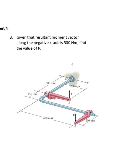
3. Given that resultant moment vector
along the negative x-axis is 500 Nm, find
the value of F.
300 mim
200 mm
150 mm
400 mm
200 mm
Expert Solution
This question has been solved!
Explore an expertly crafted, step-by-step solution for a thorough understanding of key concepts.

Step by step
Solved in 3 steps with 4 images

Knowledge Booster


Learn more about
Need a deep-dive on the concept behind this application? Look no further. Learn more about this topic, civil-engineering and related others by exploring similar questions and additional content below.Recommended textbooks for you