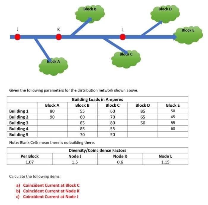
Given the following parameters for the distribution network shown above: Building Loads in Amperes Block A Block B Block C Block D Block E Building 1 Building 2 Building 3 Building 4 Building 5 80 90 55 60 85 50 60 70 65 45 65 80 50 55 85 55 60 70 50 Note: Blank Cells mean there is no building there. Diversity/Coincidence Factors Per Block Node J Node K Node L 1.07 1.5 0.6 1.15
Q: A short transmission line is represented by an impedance of 0.01 + jo.04. What is the voltage…
A: Given data, A short transmission line has Z=0.01+j0.04 ΩI=1.93∠-8° puVs=1∠0° pu
Q: In three phase transmission line system with no transposition have the inductance matrix as shown…
A:
Q: z/2 z/2 R/2 R/2 X/2 X/2 Vs V. Nominal T model of a Medium Line Circuit Globe Figure 2 (a) The…
A:
Q: A 1-phase, 20 km line delivers a load of 12 MW at 11 kV having a lagging p.f. of 0.8 at the…
A: In this answer we will find the sending end voltage and the regulation of transmission line as…
Q: For the two port network shown. Calculate the maximum average load power. Z11=3.752 0.5A Z12=-3.1252…
A: The source transformation is used to convert the practical current source into practical voltage…
Q: The bus admittance matrix of a power system is given as 1 1[-j 50 + j 10 2 +j 10 - j 30 +j 10 3 +j5…
A:
Q: Q4: Lossless transmission line of 0.25 having Z. ZL = 40 + j 30 . Find the following numerically…
A: We need to find out input impedance and reflection coefficient and standing wave ratio .
Q: Given the following line impedance of a four-bus system, obtain its admittance matrix. Line (bus to…
A: The power system is made of many transmission lines. The transmission lines have their admittance.…
Q: Shunt capacitors are installed at the receiving end to improve the line performance of a…
A: A=0.9950B=36.2266Xcsh=B1-A=36.22661-0.9950=7245.32
Q: 2. A 3-phase transmission line, 160 km long, has the following constants : Resistance/phase/km = 0-2…
A: In this question, We need to determine the sending end voltage and sending end current?
Q: Example 6.3 A 60-Hz, 230-km, three-phase overhead transmission line has a series impedance z =…
A: Given:impedance, z =0.8431 < 79.04°Ω/kmshunt addmiran y = 5.105×10⁶<90 °s/kmf = 60 Hzlength…
Q: 2. A 3-phase transmission line, 160 km long, has the following constants : = 0-2 2…
A: In this question, find the sending end voltage and sending end current. All parameters of the…
Q: Z, Source Transmission line Load
A:
Q: A 3-phase transmission line, 160 km long, has the following constants: Resistance/phase/km= 0.2 ohm…
A:
Q: Three phase transmission line requires the larger cross section area than single phase transmission…
A:
Q: The key difference between circuit theory and transmission line theory is Lumped elements…
A: key difference between circuit theory and transmission line theory
Q: A 1-phase, 20 km line delivers a load of 12 MW at 22 kV having a lagging p.f. of 0.65 at the…
A:
Q: A 3-phase, 50 Hz transmission line 100 km long delivers 20 MW at 0-9 p.f. lagging and at 110 kV. The…
A:
Q: If the power system has 'n' number of generators, then the size of the B- coefficient matrix is…
A: As per the guidelines of Bartleby we supposed to answer first question only for remaining questions…
Q: 4. A 300 m transmission line has following constants for total length: 4.5kn, 0.15mH, 60mS, 12 nF.…
A: Given length of the transmission line is l=300 m Calculate all parameters per meter R=4.5 kΩR=15…
Q: Problem statement: A three phase 60- Hz, 550- kV transmission line is 300 km long. The line…
A: we have given ;A three phase system frequency f=60Hzsource voltage =550kVlength of transmission line…
Q: In two-port networks na imum power is delivered tu the load when ZL=Zth (or * .ZL=Zth*) True False…
A:
Q: If a transmission line of characteristic impedance 50 N is terminated with a load impedance of 150…
A: Given information: The characteristic impedance of the transmission line is Z0=50 Ω The load…
Q: single phase, 50Hz transmission line connected between two buses having line resistance of 3Ω,…
A:
Q: For the two port network shown. Calculate the maximum average load power. Z11=3.75N 0.5A Z12=-3.1252…
A:
Q: A transmission line is delivering a load of 40 MW at 110 kV and 80% lagging power factor. If the…
A: Types of Power Transmission line Short Transmission line Medium Transmission line Long Transmission…
Q: Erample: A 3-o transmission line 250 km long has the following constants: Resistance/phase/km = 0-16…
A:
Q: IN A single line bus system with the impedance characterized of the following R= 0.15pu while XL=…
A: Given that Resistance in perunit R = 0.15 Reactance in perunit XL = 0.45 Impedance in perunit =…
Q: Problem 4. A 220-kV, three-phase transmission line has a per phase series impedance z = 0.005 +…
A:
Q: For the two port network shown. Calculate the maximum average load power. Z11=3.752 0.5A Z12=-3.125N…
A: PRESENCE OF SOURCE: In the presence of sources all the passive elements which are R, L and C always…
Q: Calculate the impedance parameters for the two port network Verify the result by using both methods…
A:
Q: The ABCD constants of a 3-phase transmission line are A = D = 0.841° B= 170Z85° C = 0.002Z90.4° mho…
A: In this question, choose the correct option Find the Receiving end voltage VR ? We know Vs =…
Q: A (medium) single phase transmission line 100 km long has the following constants : Resistance/km =…
A: End Condenser Method: The capacitance of the line is lumped at the load end. At the load end this…
Q: The bus impedance matrix for the 3-bus system is: 30.183 j0.078 j0.141 Z- 30.078 j0.148 0.106 j0.141…
A: In this question we need to find a new term of Z12 .
Q: Example: A 3-ø transmission line 250 km long has the following constants: Resistance/phase/km = 0-16…
A:
Q: In short transmission line calculations, the effects of the line capacitance are neglected because…
A:
Q: 2. A 3-phase transmission line, 160 km long, has the following constants : Resistance/phase/km…
A: The solution can be achieved as follows.
Q: A 3-phase, 50 Hz, 100 km transmission line has the following constants ; Resistance/phase/km = 0·1 Ω…
A:
Q: A 130 kV, 50 Hz, 3-phase transmission line delivers a load of 58 MW at 0.88 p.f. lagging at the…
A:
Q: in a single line bus system with the impedance characterizes of the following R = 0.15pu while XL =…
A: Single line bus system with the impedance R = 0.15pu , XL = 0.45pu. find the inverse of the…
Q: A 50 Hz, three-phase, 400 kV, 200 km transmission line has the following parameters Series…
A:
Q: the regulation of line at this pf and at a pf of 0.7 lead, system voltage is 220kV. L Transmission…
A:
Q: he parameters of the 500km long transmission line are impedance z = 0.1 + j * 0.4ohm / km and…
A: Given data: Series impedance, Z=0.1+j0.4 Ω/km Shunt admittance, Y=j4.2 Ω/km Frequency, f = 50 Hz…
Q: The shunt admittance and series impedance of a long transmission line are given with respect to…
A:
Q: Find the value of VDs for the given network if loss= 8 mA VDD +12 V RD 1.0 ΚΩ (1) VDS RG 10 ΜΩ
A: In this question, We need to determine the voltage Drain to source VDS ?
Q: The power obtained at the receiving end of a transmission line is generally less than the sending…
A: The power obtained at the receiving end of a transmission line is generally less than the sending
Q: A transmission line is delivering a load of 40 MW at 110 kV and 80% lagging power factor. If the…
A: Types of Power Transmission line Short Transmission line Medium Transmission line Long Transmission…
Q: Q4. A single phase overhead transmission line has a supply voltage of 34 kV and a sending end…
A:
Q: A 1-phase, 20 km line delivers a load of 12 MW at 11 kV having a lagging p.f. of 0.9 at the…
A: Sending end voltage= receiving end voltage+voltage drop in line . Regulation =( sending end voltage-…
Q: For the two port network shown. Calculate the maximum average load power. Z11=3.752 0.5A Z12=-3.1252…
A:
Step by step
Solved in 2 steps
- Let a series RLC network be connected to a source voltage V, drawing a current I. (a) In terms of the load impedance Z=ZZ, find expressions for P and Q, from complex power considerations. (b) Express p(t) in terms of P and Q, by choosing i(t)=2Icost. (c) For the case of Z=R+jL+1/jC, interpret the result of part (b) in terms of P,QL, and Qc. In particular, if 2LC=1, when the inductive and capacitive reactances cancel, comment on what happens.A single phase, 50Hz transmission line connected between two buses having line resistance of 3Ω, inductive reactance of 0.2 Henry. Both the ends of transmission lines are connected with series capacitors of 400microfarads each for series compensation. Then series impedance of the line is a.(3-j31) Ω b.(3-j59.6) Ω c.(3+j31)Ω d.(3+j59.6) Ω 2- Fast decoupled algorithm is not as accurate as the exact Newton Raphson algorithm for Variable number of iteration Fixed number of iteration Variable time per iteration Fixed time per iterationCalculate the Thevenin impedance at each bus given the impedances below: Z_line1to2 = 1.5507m + j0.0212 Ω Z_line2to3 = 5.2917m + j0.0722 Ω Z_G1 = 0.75Ω Z_G2 = 0.0184Ω Z_G3 = 0.0348Ω Z_T1 = 0.25Ω Z_T2 = 0.125Ω Z_T3 = 0.25Ω
- The load flow data for the sample power system are given below. The voltage magnitude at bus 2 is to be maintained at 1.04 p.u.Determine the set of load flow equations at the end of first iteration by using N-R method. Impedance for sample system Bus Code Impedances line charging admittance 1-2 0.08 + j0.24 0.0 1-3 0.02 + j0.06 0.0 2-3 0.06 + j0.18 0.0 Schedule of generation and loads: Bus Code Assured Voltages Generation Load…electrical engg .fig.shows a single-line diagram of a power system where the generator is connected to the bus 1 and the load is connected to the bus 2. The line impedance is 0.12 +j 0.23 pu on a 100 MVA a base. Per unit real power and reactive power supplied to the load are 0.50 and 0.30 respectively. Bus 1 is a slack bus. Use Gauss-Seidel method to determine the (i) voltage at bus 2, (ii) slack bus real and reactive powers, (iii) line flows,L-L (line) voltage of the 3-phase 50 Hz 70 km transmission line is 230 kV on the receiver (demand) side, its total impedance is R = 1 Ω / phase, L = 90 mH / phase. On the demand side, the load is powered by 80 MW power and 0.85 lagging power factor. a. Calculate the line-neutral (L-N) and line-line (L-L) voltages on the production side. b. Calculate the regulation as a percentage c. Calculate the efficiency.
- Four industrial centers are located at the corners of a square of 35300 m side. The loads are 430000 W, 600000 W, 220000 W and 740000 W respectively. Determine the best Y coordinate location of the substation . The reference point of load is 220000 W. Coordinate of Y in KM =S.1) The serial impedance per phase of a three-phase 45 km energy transmission line is 2 + j4 / phase. A load with a power factor of cos2 = 0.8 forward is fed from the end of the line. Since the line voltage at the beginning and end of the line of the energy transmission line is wanted to be kept constant at 115 kV, a) Active and reactive powers drawn from the beginning and end of the line, b) Calculating the power consumed along the energy transmission line and the efficiency of the line. S.2) Line constants of an energy transmission line are given as A = D = 0.8746 + j0, B = 0 + j128.34, C = j0.0018316 S. At the beginning of the line, it is desired to write 1920 MW active power and 600 MVAr reactive power lines under 7650kV line voltage. According to this business, a) Calculate the line end magnitudes (U2, I2 and P2). b) What value does the end voltage take when the load fed from the end of the line is deactivated? S.3) The length of a phased energy transmission line with a…Shown are two buses connected via a transmission line. Connected to Bus 1 is a generator(modelled as a voltage source V1), and to Bus 2 is a generator( with Voltage V2) and a load. The line impedance Z = R + jX is not known. Three-phase load is forecasted as 100MW + 60MVar. Generator at Bus 2 is scheduled to deliver 40MW and its excitation is adjusted for the machine to deliver 55 MVar. Voltage at Bus 1 is 241 KV angle 10 deg, while voltage at bus is 230 kV; use V2 as the reference for all angles. 1. What is the current (RMS) in amperes drawn by the load connected to Bus 2? 2. How much real power (in MW) is delivered by the generator connected to Bus 1? 3. What is the total real power loss along the line, in percent of the load? 4. What is the X/R Ratio of the line impedance?
- Determine the output impedance (Zo) for the given network with the following conditions: gfs = 3000uS and gos = 50uS. a. 10M-ohms b. 20K-ohms d. 3.33k-ohms d. 2.83k-ohmsFind the following: the power drawn by the 100ohm variable resistor If the variable resistor is set to 200-ohms, instead of 100-ohms, What is the power drawn by the 200-ohms resistor? total current of the system Is the circuit inductive, capacitive, or neither (resistive)? NOTE: Polar form for Voltage & Current. Rectangular form for ImpedanceQuestion 1a) A network comprises of n buses. The voltage, current, active power, reactive power and admittance related to the k th bus are defined as Vk, Ik, Pk, Qk and Ykk. Deduce the following:i) Related load flow equationii) Gauss-Seidel algorithm for the load flow equation