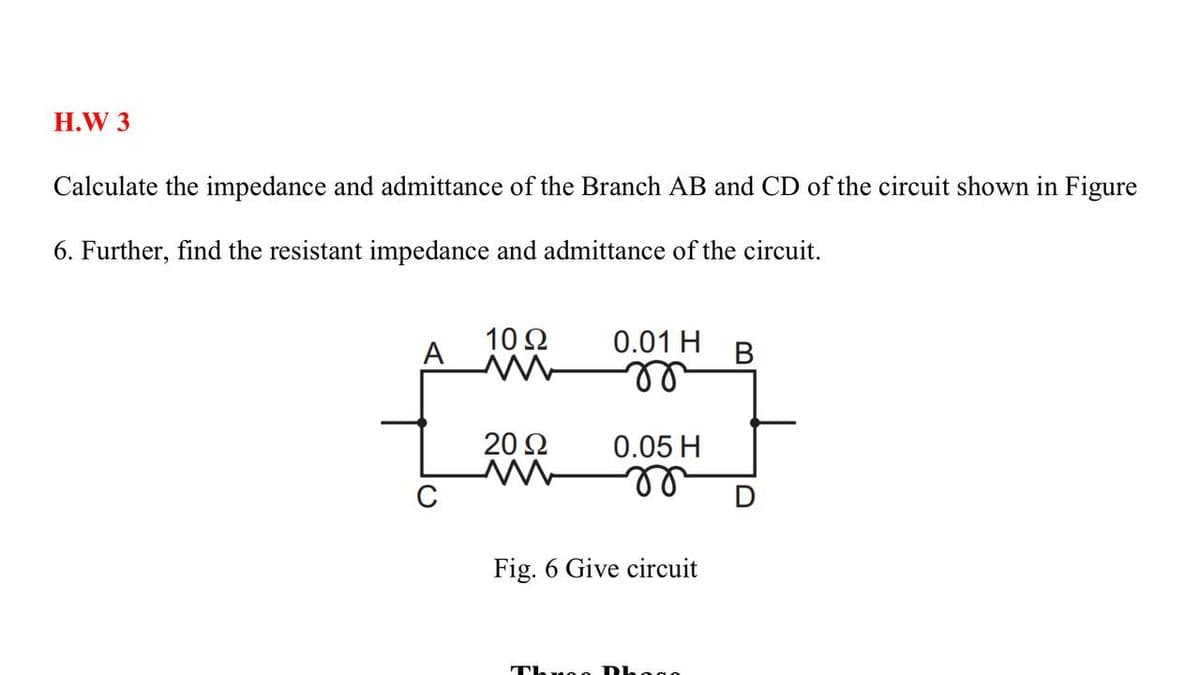
H.W 3 Calculate the impedance and admittance of the Branch AB and CD of the circuit shown in Figure 6. Further, find the resistant impedance and admittance of the circuit. 10Ω 0.01 H A ll 20 2 0.05 H C Fig. 6 Give circuit
Q: www.nitropdf.com Engineering Circuit Analysis 8* Edition Chapter Four Exercise Solutions 58. One…
A: Design a circuit to 1.make the controlling quantity 8v1 i.e depends on a nodal voltage. 2..make the…
Q: i2 2Ω 3Ω # 3 8 V 4 A Determine the three mesh currents in Fig. 4.24a. 2 N 3Ω (a) We note that 4A…
A: The mesh analysis includes the currents that flow in a loop. The mesh analysis uses the…
Q: If a d.c. supply of 180 V is connected across terminals AB in Fig. 2.20, then current in 6 resistor…
A: Given circuit, Supply voltage, V = 180 V
Q: 5. Find the unknown currents in the curcuits shown in Fig. 2.40 (a). DC Network Theorems 4A 8A SA 5A…
A: “Since you have asked multiple questions, we will solve the first question for you. If you want any…
Q: Q.6: For the circuit shown if Vs=1020°v: 1. Find the value of "XM" that makes the Vs current through…
A: The circuit given is shown below:
Q: 2. Find the currents in through is and the voltage v, in the circuit in Fig?. 10 A 10 2 20 2 30 2 2A…
A:
Q: Q2) Find the equivalent circuit for the network external to the 7 capacitive reactance in Fig. 2.…
A:
Q: 2.4 Parallel and Series-Parallel Configurations 10. Determine V, and Ip for the networks of Fig.…
A:
Q: 6. a. Find the Thévenin equivalent circuit for the network external to the resistor R in each of the…
A: From the Thevenins equivalent Circuit
Q: Parallel e-connect the circuit as shown in Fig.6, and set the supply to 10 v. measure the current in…
A:
Q: B) For the circuit shown in Fig. (6). Determine the Norton equivalent between a and b. XL YL 80 2 20…
A:
Q: +12 I, = 2 mA VasoFF = -6 V 1.8 kN 1.0 kN Determine R1 a) Vps 1.0 kN 2.0 kN 1.5 kN b) Im c) Ay,
A:
Q: For the circuit shown, Determine the following: (a) hie (b) Av (c) Ai (d) VL(p-p) if Rs connected is…
A: Given circuit is Common emitter with emitter resistance bypassed.
Q: For the circuit shown in Fig. 2, calculate the current flowing through 30 2 resistor by applying…
A: The solution is given below
Q: 2.8 Design a problem, complete with a solution, to help ead other students better understand…
A: Need to apply KCL to design for i1,i2,i3
Q: Find V, in the network in Fig 5 using Thévenin's theorem. 1000 Ix 6 kN 1 ΚΩ 3V(+ 1 mA 2 k : Vo Fig.…
A:
Q: For the Darlington network of Fig. 5.181: Find the currents IB₁. +16 V 2.4 ΜΩ B₁=50, B₂=120 VBE,…
A: Darlington transistor :- The combination of multi- transistor is called Darlington configuration…
Q: 7.1 Consider PV module A whose characteristics are shown in Table 7.3. Com- pute: The cell…
A: Since the question given by you contain multiple subparts and you have not specified which one to…
Q: Answer all questions Q1 Find the Thévenin equivalent circuit for the network external to the…
A:
Q: 6. a. Find the Thévenin equivalent circuit for the network external to the resistor R in each of the…
A: Whenever we will open circuit the load resistance are then voltage across the 12 ohm resistor will…
Q: ) Write (but do not solve) the mesh current and node voltage equations by inspection 3 2s (directly)…
A: In this question, Write the mesh and nodal analysis equation in the circuit. Here 4 nodes and 5…
Q: 2. Connect the circuit shown in Fig.(5). Change the resistor value from 50- 5002, measure current,…
A: Voltage across a resistor = Current flowing through the resistor X Resistance Current flowing…
Q: H.W.: For the circuit of Fig. 1.8, determine the nodal voltage vl if A is (a) 2i1; (b) 2vi. 2Ω 2Ω 5…
A:
Q: For the etwork of Fig. 6.83: Fad the carent !. A Deermine the vwtage Calulate the source current 1…
A: Need to find currents and voltage for the given circuit
Q: HW22(E ) For the common-base network of Fig. 5.187 : a. Determine (Z i) and (Zo). b. Calculate( Av)…
A:
Q: Potentiometer: The resistive wire AB in the circuit shown has the length of 100cm. When switch S is…
A: The balance condition of the potentiometer is mentioned when the length is equal to. L1 =0.4 m The…
Q: CIRCUITS-DIRECT CURRENT 16. The wiring arrangement shown in Fig, 426 is known as an Edison…
A: we need to determine EA, EB, EC and power delivered to the load A, B and C.
Q: 1. a) Obtain equivalent resistance Rab for the fig. 1. 30 2 40 2 ww 20 2 a o 10 2 80 2 60 2 50 2 bo…
A: The detailed answer is solved below according to the given parameters.
Q: Practice Problem 2.8 Find the currents and voltages in the circuit shown in Fig. 2.28. Answer: v, =…
A: We will apply nodal analysis and ohms law here According to ohms law, i= v/r
Q: Using the measured values, determine whether the algebraic sum of the currents entering and leaving…
A: according to the given circuit, if we apply kcl at node A. We get, i1= i2+i3 According to KCL, sum…
Q: 2. Given the information appearing in Fig. 4.119, determine: a. Ic. b. Rc. с. Rв. d. VCE- 12 V RC RB…
A:
Q: Q4 For the parallel network in Fig.2: 1. Find the total resistance. 2. What is the voltage across…
A: we will use KCL and ohms law to find branch current and total current. if two resistors are in…
Q: For the circuit shown in Fig. 2, find the Norton equivalent with IN referenced positive toward…
A: In this question, find the Norton equivalent circuit across the terminal a and b.
Q: 100 mA DC(A) 10 V DC 10 V R, Measuring the component current through a resistor in a circuit with…
A:
Q: Q5) For the network in Fig. 5. a. Find the total impedance Zr and the total admittance YT. b. Find…
A: Given circuit:
Q: write three node equations for nodes A, B, and C, with node D as the reference, and find the node…
A: This question belongs to circuit theory . It is based on the concept of calculation of voltages at…
Q: HW22(C) For the network of Problem 13: 12 V a. Determine (re) . b. Find (hfe )and (hie). c. Find…
A: Brief description : For the given bipolar junction transistor we need to calculate the value of…
Q: Write (but do not solve) the mesh current and node voltage equations by inspection (directly) for…
A: In this question, A circuit is given, Write the mesh analysis equations and node equation.
Q: Q3 For the network of Fig.3, write the mesh equations. Then, solve these equations u determinant…
A:
Q: EXAMPLE 5.8 For the network of Fig. 5.44, determine: a. re b. Z. c. Z d. Ay. e. Aj. 10 uF 10 uF I ka…
A:
Q: In Fig. below the current is 5 A If a short circuit should develop across the 2 2 resistor, 1. find…
A: KIRCHHOFF’S LAW KCL: The algebraic sum of all currents at a node is zero. KCL is…
Q: *11. Find Vs for the network of Fig. 7.84. 20 V 2.2 k2 Ipss = 4.5 mA Vps Vp =-5 V I ss = 6 mA Vp =…
A:
Q: What is the equivalent resistance of the ladder network shown in Fig. 2.41? Α 25Ω Ε 50Ω G 50Ω Κ 25Ω…
A: We have an circuit as shown in figure , We have been asked to find the , the equivalent…
Q: 16 V 24. For the network of Fig. 5.162: a. Determiner, and Bre. b. Find Z, and Z,. c. Calculate Ay.…
A: The circuit diagram is shown below, Where, β=110r0=50kΩ
Q: 93:8 Determine the values of V, and V, and the currents i, and i, in the cct shown in fig. 6 10 Ka…
A: Since you have posted a question with multiple independent question, we will solve the first…
Q: For the common-base network of Fig. 5.187 : a. Determine (Z i) and (Zo). b. Calculate( Av) and (Ai)…
A: Brief description : For the given BJT common base amplifier circuit we need to derive the value of…
Q: H.W.: For the circuit of Fig. 1.8, determine the nodal voltage vl if A is (a) 2ir;) (b) 2vi. 5 A A.…
A: Let's use the concept of nodal analysis to solve this problem and find the value of V1 in two…
Q: (Network) Show that by Kirchhoff's voltage law (Sec. 2.9), the currents in the network in Fig. 150…
A:
Q: EXAMPLE 6 For the network of Fig. (6), determine the value of R for maximum power to R, and…
A:
Q: Problem 30. 31. For the network of Fig. 6.97: a. Determine the open-circuit voltage V. b. If the…
A: Say if Vx is the voltage across now we we have to find VL for various circuit.
Step by step
Solved in 5 steps with 13 images
- Convert the following instantaneous currents to phasors, using cos(t) as the reference. Give your answers in both rectangular and polar form. (a) i(t)=5002cos(t30) (b) i(t)=4sin(t+30) (c) i(t)=5cos(t15)+42sin(t+30)Given the complex numbers A1=630 and A2=4+j5, (a) convert A1 to rectangular form: (b) convert A2 to polar and exponential form: (c) calculate A3=(A1+A2), giving your answer in polar form: (d) calculate A4=A1A2, giving your answer in rectangular form: (e) calculate A5=A1/(A2*) giving your answer in exponential form.A circuit consists of an AC voltage source, a 10-ohm resistor, and a capacitor, all connected in series. The magnitude of the impedance of the capacitor is also 10 ohms. Which of the following is true about the source voltage and the current through the circuit? a. Insufficient information is given. b. The source voltage will lag the current. c. The source voltage will lead the current. d. The source voltage will be in-phase with the current.
- A capacitor and a resistor are connected in parallel to a 120-V, 60-Hz line. The resistor has a resistance of 40 Ω, and the capacitor has a capacitance of 132.6 µF. What is the total current flow through the circuit? What is the impedance of the circuit?What is the power factor of the circuit? How many degrees out of phase are the current and voltage?PLEASE SOLVE THE LETTERS D & E. PLEASE SHOW YOUR DETAILED SOLUTION. WILL GET A LIKE A 25- W resistor and a 40-µF capacitor are connected in parallel across a 120-V, 50-Hz source. Determine the magnitude of the following: (a) admittance; (b) current through resistor and capacitor; (c) the total current; (d) true power and capacitive reactive power; (e) apparent power, power factor, and power factor.PLEASE SHOW YOUR DETAILED SOLUTION. WILL GET A LIKE A 25- W resistor and a 40-µF capacitor are connected in parallel across a 120-V, 50-Hz source. Determine the magnitude of the following: (a) admittance; (b) current through resistor and capacitor; (c) the total current; (d) true power and capacitive reactive power; (e) apparent power, power factor, and power factor.
- A 5-ohm resistor is connected in series with a 25 micro-farad capacitor. A source voltage of158 volts, 50 Hz supplies the combination. Determine the following:a. Circulating currentb. Voltage across the resistorc. Voltage across the capacitord. Real power supplied by the sourcean R-L circuit takes a current of 7amp that lags behind the 231-volt source by 35elec deg. calculate the power factor, power, impedance, resistance, and inductive reactance of the circuit.25/. A three phase loads each resistance of 100 Ω and capacitance of 10 µF are given, with 415 V, 50 Hz supply. Find the total power for i) Star Connection ii) Delta Connection iii) Draw and Compare your result for both the cases
- Given the circuit shown below, if Zx = 100/0 o determine the current in each branch by: a) Nodal Methodb) Maxwell’sMethodPLEASE ANSWER LETTERS D & E PLEASE SHOW YOUR DETAILED SOLUTION. WILL GET A LIKE A 25- W resistor and a 300-mH inductor are connected in parallel across a 120-V, 50-Hz source. Determine the magnitude of the following: (a) admittance; (b) current through resistor and inductor; (c) the total current; (d) true power and inductive reactive power; (e) apparent power, power factor, and power factor angle.Each phase of a wye-connected load consists of a 50-Ω resistance in parallel with a 100-μF capacitance. Find the impedance of each phase of an equivalent delta-connected load. The frequency of operation is 60 Hz.