H.W: Draw a logic diagram to implement the following register transfers: (a) If the content of the 8-bit register R is odd, then -X xor y else x -x.y (logic AND) Assume x and y are 8 bits wide. (b) If the number in the 8-bit register R is negative, then x– x-1 else x - x+1. Assume x and y are 4 bits wide.
H.W: Draw a logic diagram to implement the following register transfers: (a) If the content of the 8-bit register R is odd, then -X xor y else x -x.y (logic AND) Assume x and y are 8 bits wide. (b) If the number in the 8-bit register R is negative, then x– x-1 else x - x+1. Assume x and y are 4 bits wide.

Chapter4: Processor Technology And Architecture
Section: Chapter Questions
Problem 22VE: Two 1-bit values generate a 1 result value when a(n) _____ instruction is executed. All other input...

Related questions

Question
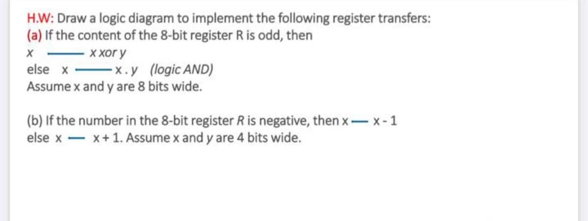
Transcribed Image Text:H.W: Draw a logic diagram to implement the following register transfers:
(a) If the content of the 8-bit register R is odd, then
ххог у
else x -x.y (logic AND)
Assume x and y are 8 bits wide.
(b) If the number in the 8-bit register R is negative, then x- x-1
else x - x+1. Assume x and y are 4 bits wide.
Expert Solution
This question has been solved!
Explore an expertly crafted, step-by-step solution for a thorough understanding of key concepts.

Step by step
Solved in 3 steps with 5 images

Knowledge Booster


Learn more about
Need a deep-dive on the concept behind this application? Look no further. Learn more about this topic, computer-science and related others by exploring similar questions and additional content below.Recommended textbooks for you
Systems Architecture
Computer Science
ISBN:
9781305080195
Author:
Stephen D. Burd
Publisher:
Cengage Learning
Systems Architecture
Computer Science
ISBN:
9781305080195
Author:
Stephen D. Burd
Publisher:
Cengage Learning