Hi i am looking for an answer to question 2 please

Chapter59: Motor Startup And Troubleshooting Basics
Section: Chapter Questions
Problem 12SQ: How is a solid-state diode tested? Explain.

Related questions

Question
100%
Hi i am looking for an answer to question 2 please
Transcribed Image Text:PRELAB EXERCISES'
+
R
C=
VC
Vi
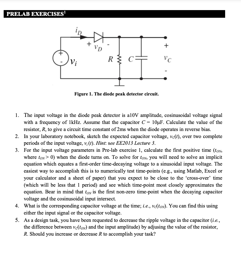
Figure 1. The diode peak detector circuit.
1. The input voltage in the diode peak detector is al10V amplitude, cosinusoidal voltage signal
with a frequency of 1kHz. Assume that the capacitor C = 10µF. Calculate the value of the
resistor, R, to give a circuit time constant of 2ms when the diode operates in reverse bias.
2. In your laboratory notebook, sketch the expected capacitor voltage, vɖt), over two complete
periods of the input voltage, v, (f). Hint: see EE2013 Lecture 3.
3. For the input voltage parameters in Pre-lab exercise 1, calculate the first positive time (ton,
where ton> 0) when the diode turns on. To solve for ton, you will need to solve an implicit
equation which equates a first-order time-decaying voltage to a sinusoidal input voltage. The
easiest way to accomplish this is to numerically test time-points (e.g., using Matlab, Excel or
your calculator and a sheet of paper) that you expect to be close to the 'cross-over’ time
(which will be less that 1 period) and see which time-point most closely approximates the
equation. Bear in mind that ton is the first non-zero time-point when the decaying capacitor
voltage and the cosinusoidal input intersect.
4. What is the corresponding capacitor voltage at the time; i.e., vɖton). You can find this using
either the input signal or the capacitor voltage.
5. As a design task, you have been requested to decrease the ripple voltage in the capacitor (i.e.,
the difference between v(ton) and the input amplitude) by adjusing the value of the resistor,
R. Should you increase or decrease R to accomplish your task?
Expert Solution
This question has been solved!
Explore an expertly crafted, step-by-step solution for a thorough understanding of key concepts.

Step by step
Solved in 2 steps with 2 images

Knowledge Booster


Learn more about
Need a deep-dive on the concept behind this application? Look no further. Learn more about this topic, electrical-engineering and related others by exploring similar questions and additional content below.Recommended textbooks for you