I2 VR2 The diagram shows the Op Amp circuit – Inverting Amplifier – in which you should calculate the output current of the Op Amp chip. R2 IOUT IR1 VR1 + R + In each problem, assume that both “Golden Rules" apply, and neglect voltage clipping. IR3 VOUT R3 Ve
I2 VR2 The diagram shows the Op Amp circuit – Inverting Amplifier – in which you should calculate the output current of the Op Amp chip. R2 IOUT IR1 VR1 + R + In each problem, assume that both “Golden Rules" apply, and neglect voltage clipping. IR3 VOUT R3 Ve

Power System Analysis and Design (MindTap Course List)
6th Edition
ISBN:9781305632134
Author:J. Duncan Glover, Thomas Overbye, Mulukutla S. Sarma
Publisher:J. Duncan Glover, Thomas Overbye, Mulukutla S. Sarma
Chapter12: Power System Controls
Section: Chapter Questions
Problem 12.3P

Related questions
Question
it's urgent please solve asap
Transcribed Image Text:Ir2
VR2
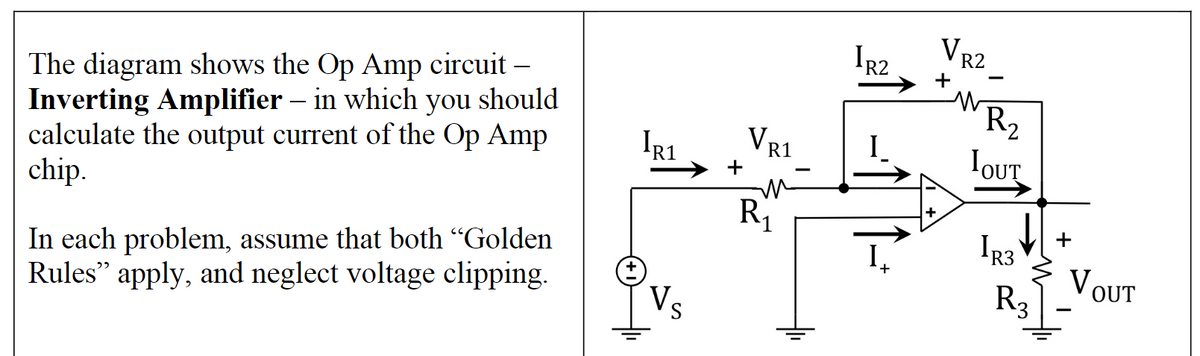
The diagram shows the Op Amp circuit –
Inverting Amplifier – in which you should
calculate the output current of the Op Amp
chip.
+
R2
IOUT
IR1
+
VR1
Rj
+
I3
In each problem, assume that both “Golden
Rules" apply, and neglect voltage clipping.
VOUT
R3
Vs
Expert Solution
This question has been solved!
Explore an expertly crafted, step-by-step solution for a thorough understanding of key concepts.

Step by step
Solved in 2 steps with 1 images

Knowledge Booster


Learn more about
Need a deep-dive on the concept behind this application? Look no further. Learn more about this topic, electrical-engineering and related others by exploring similar questions and additional content below.Recommended textbooks for you
Power System Analysis and Design (MindTap Course …
Electrical Engineering
ISBN:
9781305632134
Author:
J. Duncan Glover, Thomas Overbye, Mulukutla S. Sarma
Publisher:
Cengage Learning
Power System Analysis and Design (MindTap Course …
Electrical Engineering
ISBN:
9781305632134
Author:
J. Duncan Glover, Thomas Overbye, Mulukutla S. Sarma
Publisher:
Cengage Learning