Ic (mA) 2.5 2.0 1.5- 1.0- 0.5 ol 0.7 V FIGURE 4-12 IB = 25 μA B = 20 μA IB = 15 μA IB = 10 μA IB=5 μA VCE
Ic (mA) 2.5 2.0 1.5- 1.0- 0.5 ol 0.7 V FIGURE 4-12 IB = 25 μA B = 20 μA IB = 15 μA IB = 10 μA IB=5 μA VCE

Chapter1: General Information For Electrical Installations
Section: Chapter Questions
Problem 14R

Related questions

Question
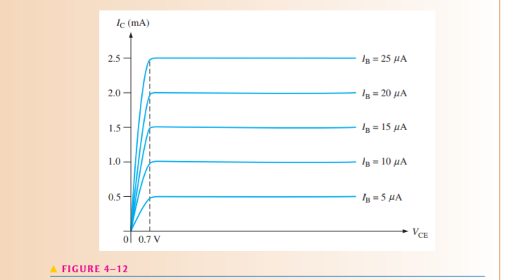
Where would the curve for IB=0 appear on the graph in Figure 4–12, neglecting col-lector leakage current?
Transcribed Image Text:Ic (mA)
2.5
2.0
1.5-
1.0-
0.5
ol 0.7 V
FIGURE 4-12
IB = 25 μA
B = 20 μA
IB = 15 μA
IB = 10 μA
IB=5 μA
VCE
Expert Solution
This question has been solved!
Explore an expertly crafted, step-by-step solution for a thorough understanding of key concepts.

Step by step
Solved in 2 steps

Knowledge Booster


Learn more about
Need a deep-dive on the concept behind this application? Look no further. Learn more about this topic, electrical-engineering and related others by exploring similar questions and additional content below.Recommended textbooks for you
EBK ELECTRICAL WIRING RESIDENTIAL
Electrical Engineering
ISBN:
9781337516549
Author:
Simmons
Publisher:
CENGAGE LEARNING - CONSIGNMENT

Electricity for Refrigeration, Heating, and Air C…
Mechanical Engineering
ISBN:
9781337399128
Author:
Russell E. Smith
Publisher:
Cengage Learning
EBK ELECTRICAL WIRING RESIDENTIAL
Electrical Engineering
ISBN:
9781337516549
Author:
Simmons
Publisher:
CENGAGE LEARNING - CONSIGNMENT
Electricity for Refrigeration, Heating, and Air C…
Mechanical Engineering
ISBN:
9781337399128
Author:
Russell E. Smith
Publisher:
Cengage Learning