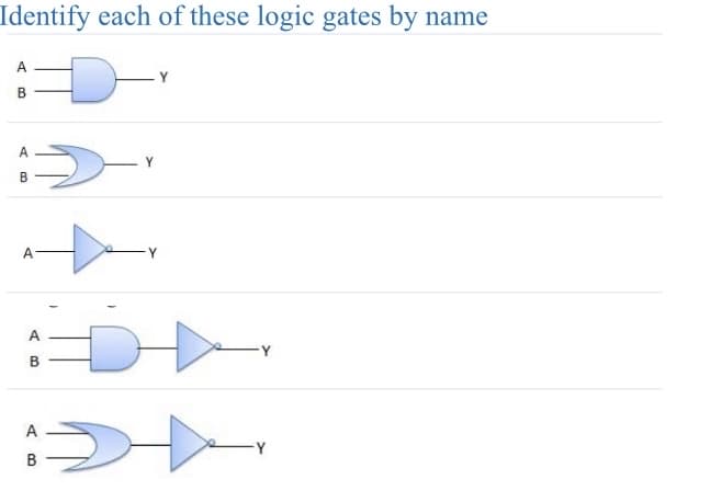
Identify each of these logic gates by D A B A B A A B A B - Y Y


Q: Q3 (a) Referring to Figure Q3.1, i(t) 5 01 12 3 45 56 7 8 9 10 r(s)
A: Given:we need to do:a) determine the rms value of the waveform. b) based on above answer, compute…
Q: The signal x(t) = 10cos (40nt +)+20sin (70nt +): O 1. Is aperiodic O 2. Has a fundamental period of…
A:
Q: Given a scalar electric field expression: E (x, t) = cos(x + wt) + cos(x - wt) a. Show that it…
A: The wave equation is a differential equation that describes the behavior of waves, such as sound…
Q: A circuit consisting of three ideal batteries with voltages & 1, 82, and 83, and three ideal…
A:
Q: 2.- Consider the network shown in the figure below. Use series and parallel reduction to calculate…
A:
Q: Given Fus) = St 5 (SH1) (² + 2₁-3) a) Determine and plot the poles and zeros of f(s) b) Use the…
A: The Laplace transform is a powerful mathematical tool used primarily in engineering and physics to…
Q: S = 600 VA, Q = 450 VAr (inductive)
A: S = 600 VA Q = 450 VARFind the complex power
Q: Create a circuit diagram for the prototype of "Motion Sensor Light Activator using Raspberry Pi…
A: According to the question, we need to create a circuit diagram for the prototype of "Motion Sensor…
Q: Problem 3: For the following input-output pairs (input x(t) and output y(t)), find the corresponding…
A:
Q: *28. Determine the power delivered to the 6 Ω Ioad in Fig. 87. E + - "Η ΖΩ Μ 24 V 12 Ω Μ 4Ω 12 Ω Μ…
A: The given circuit isWe need to determine the power delivered to the 6 Ω load.
Q: Question 6 Vin R1 Vb n D1 Given a diode circuit with Vin= 1.5 V, R1 = 1.8 kOhms, Vb = 5.9 V.…
A:
Q: 7.3 A Yagi aerial consists of a dipole of 73 + j0 22 imped- ance and a parasitic element of 81 +j108…
A:
Q: What is the inductance of the primary (L_1) and secondary coil (L_2) of a step - down transformer if…
A:
Q: draw the source with polarity and the current direction on said schematic. determine the total…
A:
Q: With vs = 12V, a. calculate the voltages v4 and v5 in Figure 1. b. calculate the currents going…
A: In the given circuit the value of the voltage across the resistor, current through the resistor and…
Q: 10.58 The impedance Z₁ in the circuit in Fig. P10.58 is ad- justed for maximum average power…
A: The impedance Z₁ in the circuit is ad- justed for maximum average power transfer to ZL The internal…
Q: Compute the total power dissipated by the circuit.
A: In the given question we need to calculate the total power dissipation in circuit.
Q: Find ZEQ1(S) and ZEQ2(S) for the bridge-T circuit shown on the right. Express each impedance as a…
A: In the given questions we need to calculate the impedance and it's pole zero location.
Q: Answer 43 • V4 = 12V • V10 = 30V ● V5 = 15V 3 A 5 10 Figure 3.10.25
A:
Q: Using a single DC power supply and 3 AC power supplies, generate the required complex waveforms A…
A:
Q: A ring-of-nine oscillator is found to operate at 20 MHz. Find the propagation delay of the inverter.
A: Given that,number of inverters in ring oscillator, Frequency of oscillator is, A ring oscillator is…
Q: Why is the width of the depletion Regen unequal in the E-type MOSFT transistor ?
A: In the given question we need to explain why depletion width will be more near drain terminal.
Q: The single-sided power spectral density function of the signal: x(t) = 10cos (40nt + ) +20sin (707t…
A: A continuous-time signal is given as:We need to determine its single-sided power spectral density…
Q: A step-down transformer has a ratio of 6:1, if the input to the transformer is 3kw at 3kv. Calculate…
A: Given data:-Transformer ratio N_1/N_2 = (6/1) Input power (P_i) = 3KWInput voltage V_(1) = 3KVKVA…
Q: Design a series RLC circuit so that the equivalent impedance ZEQ(S) has the pole-zero diagram shown…
A:
Q: Two series capacitors C1 and C2 are connected in series to a 24V battery. The dielectric for between…
A: In the given questions we need to calculate the voltage across capacitor C2.
Q: The following voltage waveform is applied to a 10 S2 resistor. Develop a program to plot voltage,…
A: Given a plot,To plot the voltage, current, power, and energy as a function of time, you can use the…
Q: Find the equivalent capacitance and inductance. C1 C2 HHH L1 m L2 m Ceq = ? Leg = ? BA
A:
Q: Consider the scenario depicted in Fig. 2.11 again. Suppose the electron concentration is equal to N…
A:
Q: 43. Find the voltage drops across the resistors in the circuit of Figure 3.10.25. Answer 43 • V₁ =…
A:
Q: 1 The NTC-type thermistor (NTC-negative thermal coefficient) has the characteristic curve shown…
A:
Q: Determine the phasor forms of the following instantaneous vector fields:
A: To determine the phasor form of the given vector field H=−10cos(106+pi/3)x^, we use the Eulers…
Q: 8. Use Norton's Theorem to find Io. 12V + 4kQ w m 3kQ. To 12kQ m D₁2 12mA
A: Given a circuit and asked to find the current indicated using norton's theorem.
Q: if an ohm meter was connected to points b and d in the following circuit, what would the measured…
A: Given here a resistor circuit and we have to calculate the resistance between b and d points.
Q: 3.2-1 Sketch the following function sinc [(лf-2л)/5];
A: In this question, we need to sketch the given function.we know, sinc(x) =
Q: Is क्य R डॉट हेरि 24 12 टिप -m डेटिड
A: Given Data:A DC resistive circuit with,Supply current To Find:The current
Q: Q.5 A hydraulic actuator block diagram is shown in Figure Q.5a. The system uses a linear variable…
A:
Q: 4. Determine the current in each of the loops of the following circuit using the Mesh Analysis…
A:
Q: 6 Is↑ Vs 12V 0 R1 12052 + VR1 - b R2 5652 + VR2- - VR4 + RA 27052 VR3 с R3 {47052 d
A:
Q: Determine the output X of the following 4-input NAND gate: A B X
A: Given:4 input NAND gate, we need to determine the output X for input combinations,
Q: en the I-V characteristics of an unknown nonlinear electronic device X.
A:
Q: 4. The circuit below is a MOSFET common-source amplifier driving a load resistor. Assume the MOSFET…
A:
Q: caculate the missing values of the output voltage y(n) above
A: Given:n0123456789--x(n)201042100000-y(n)108421------------input and impulse response we are…
Q: Based on the KCL, what is the value of 11? I1 =? A Із = ЗА I2 = 5A
A: Given:we need to determine:the value of current I1 using KCL.
Q: What is the role of SiO2 in Integrated Circuits? a) Insulating component b) Resistance component c)…
A: The purpose of SiO2 in the integrated circuits needs to be identified from the given options.
Q: High Speed Digital : A single 10V pulse is sent down a 150 transmission line with a load resistance…
A: We need to calculate the voltage when the signal reaches the load.
Q: N lamps are connected in parallel to a voltage source Vo as shown in the figure. Lamp #3 is not…
A: Number of lamps are N,SourceVoltage is Vo.These N lamps are connected in parallel to the source…
Q: 10 The system with frequency response H(w) = 3+ to x (t) = 20 cos (2t +) is: O 1. y(t) = 40 cos(2t…
A:
Q: Find the voltage and current across the 2ohm resistor. -2A4 {1Ω 1A 1Ω ww 292 M + 1 = ? V = ?
A:
Q: As shown in the figure, the two charges q1and q2 (equal in magnitude) are fixed at the corners of…
A: The objective of the question is to determine the magnitude of the charges q1 and q2 based on the…

Step by step
Solved in 3 steps with 10 images


- F(a,b,c,d)=ab'+c'd'+a'cd' Perform the function in accordance with the following styles using the Karnaugh diagram. Draw each simplification using the corresponding logic gates. a) only or not (NOR) b) and not just (NAND) c) OR-NAND d) AND-NORchoose the correct answer If a two-input logic gate produces a output of logic HIGH, only if both inputs are different, then the logic gate is? a. IC 7400 b. IC 7486 c. IC 7408 d. IC 7432Discreet Mathematics Create the logic circuit diagram for F= XY’ + XZ
- logic circuit diagram for fabinaaci counter that gives output in fabinaaci sequence.upto 2 digits please mentions the gates and ics used in circuit.choose the correct answer Logic gates from which of the following logic families are suitable for VLSI circuits? a. MOS b. ECL c. CMOS d. TTL1.Assume that one input of a two-input AND gate is connected to a square wave. If the other input is connected to a logic high, what will be present on the output? A. A constant logic high B. A square wave C. A square wave that mirrors the input square wave D. A constant logic low
- timing diagram for output versus inputs. Use minimal multilevel logic design and 2-input, 3-input NOR gates and inverter gates only to design the following: F(A, B, C, D) = ΠM((2, 4, 5, 6, 8, 10, 12, 13) · ΠD(0, 11) . I need help with the timing diagramwhat a logic function corresponds to the following arrangement? a.L =(S1 OR S2) AND (S3 OR S4)draw the logic diagram using three basic 2-input logic gates F=(A'+C) (A'+ C') (A+B+C'D)